Facial expression recognition apparatus and method, and image capturing apparatus

Active Publication Date: 2010-07-29
CANON KK
View PDF5 Cites 78 Cited by
  • Summary
  • Abstract
  • Description
  • Claims
  • Application Information

AI Technical Summary

Benefits of technology

[0008]The present invention was made with account taken of the above-described problems and provides a facial expression recognition apparatus and method wherein, in a typical embodiment, the advanc

Problems solved by technology

On the other hand, however, these processes have the following problems: (1) time and labor is required in order to register the neutral images in advance; (2) facial expressions can be recognized only for registered persons; (3) more memory areas are required because the number of images etc. subject to registration depends on the number of persons subject to facial expression recognition; (4) when the imaging environment during registration and imaging environment during facial expression recognition are different, facial expressions are sometimes impossible to recognize with accuracy due to th

Method used


Image

  • Facial expression recognition apparatus and method, and image capturing apparatus
  • Facial expression recognition apparatus and method, and image capturing apparatus
  • Facial expression recognition apparatus and method, and image capturing apparatus

Examples


embodiment 1

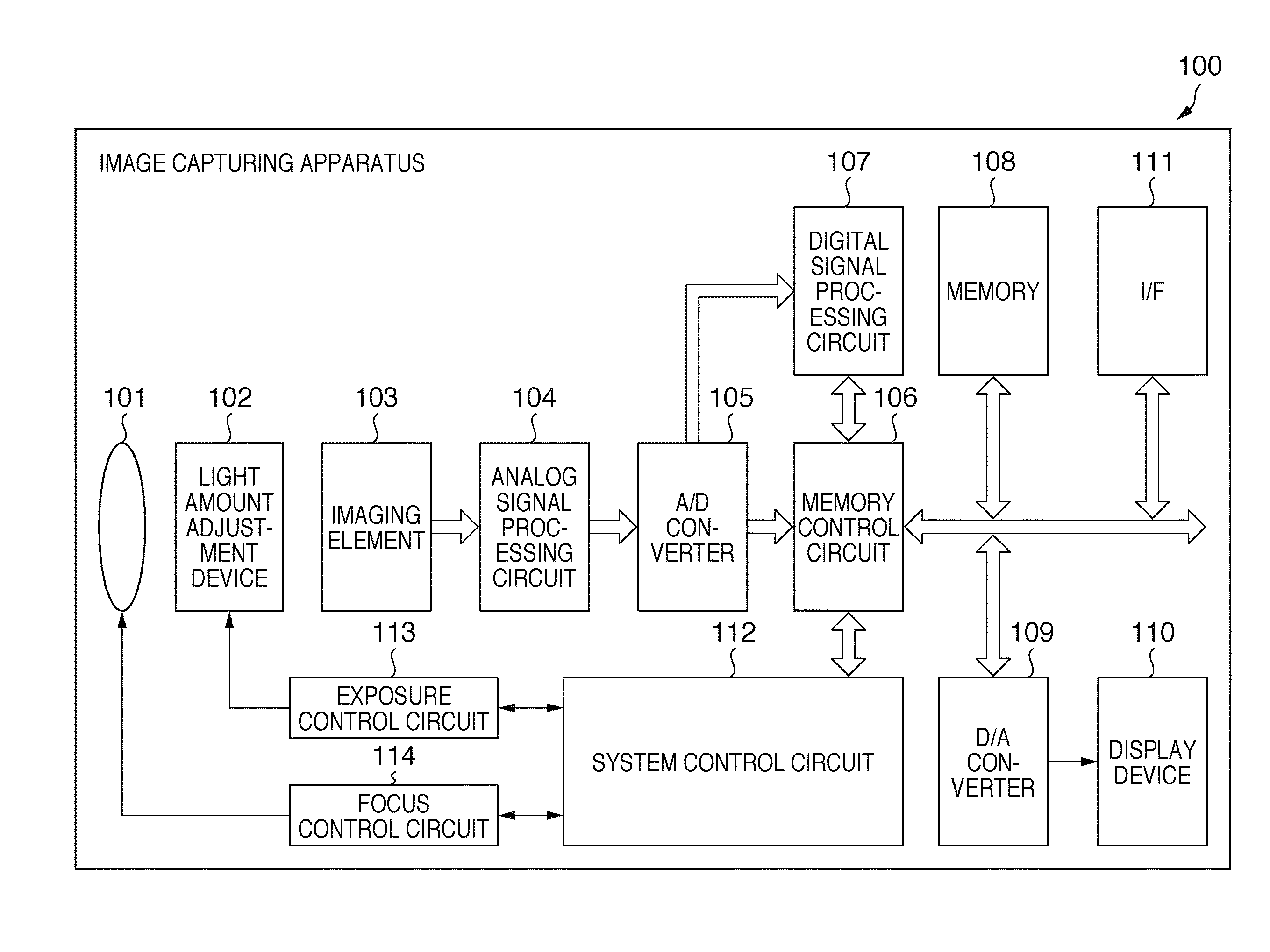
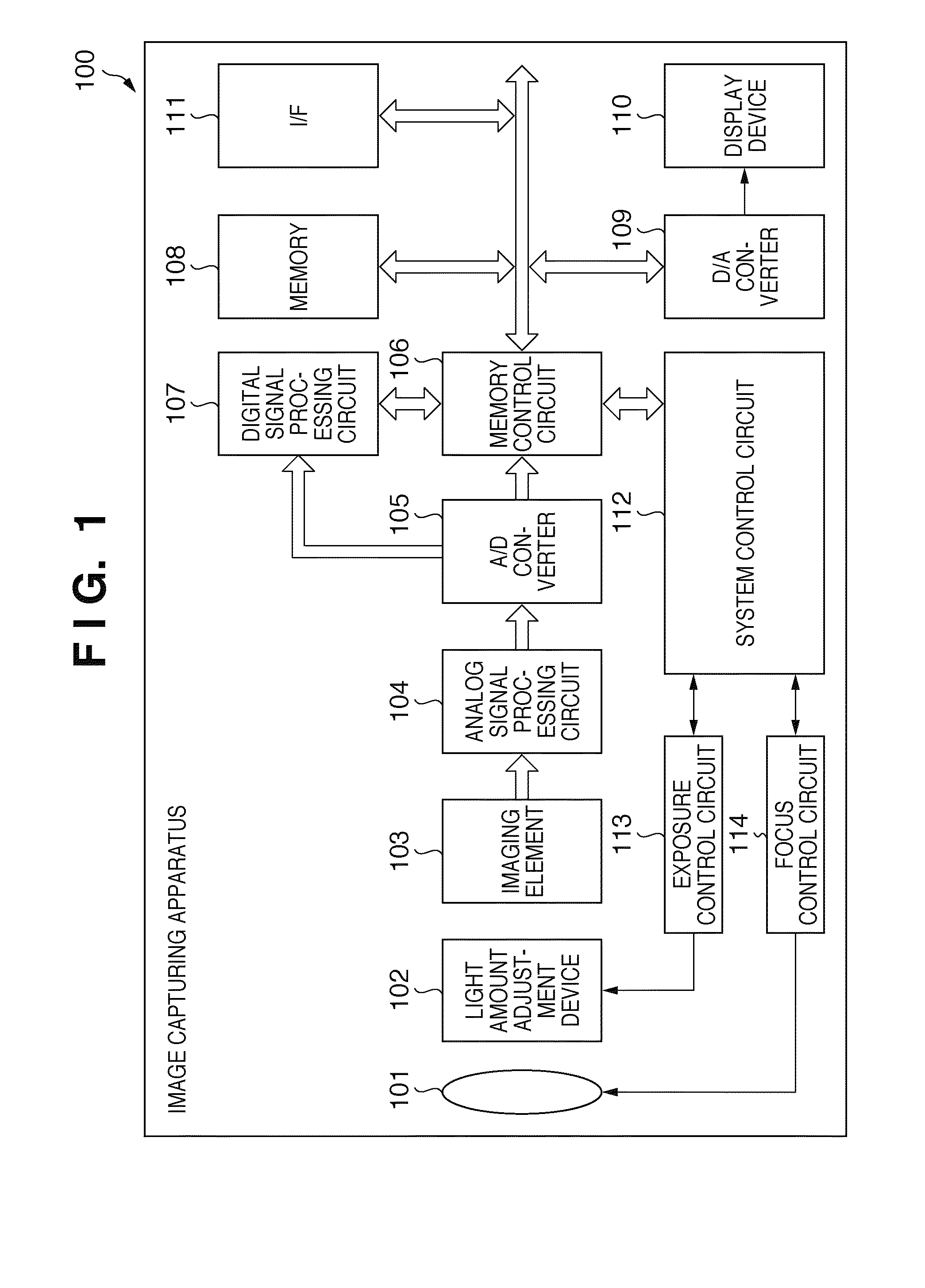
[0079]FIG. 1 is a block diagram illustrating the configuration of an image capturing apparatus 100 according to the embodiment. In the present embodiment, an electronic still camera is used as an example of the image capturing apparatus 100. Below, the image capturing apparatus 100 is also referred to as an “electronic camera”.

[0080]In FIG. 1, the numeral 101 designates an imaging lens group. The numeral 102 designates a light amount adjustment device comprising a diaphragm device and a shutter device. The numeral 103 is an imaging element that converts a luminous flux passing through the imaging lens group 101 and representing a subject image to electrical signals. The imaging element 103 is constituted, for instance, by a CCD or a CMOS, etc. The numeral 104 is an analog signal processing circuit subjecting the analog signal output of the imaging element 103 to clamping and gain processing. The numeral 105 represents an analog-to-digital (A / D below) converter converting the output ...

embodiment 2

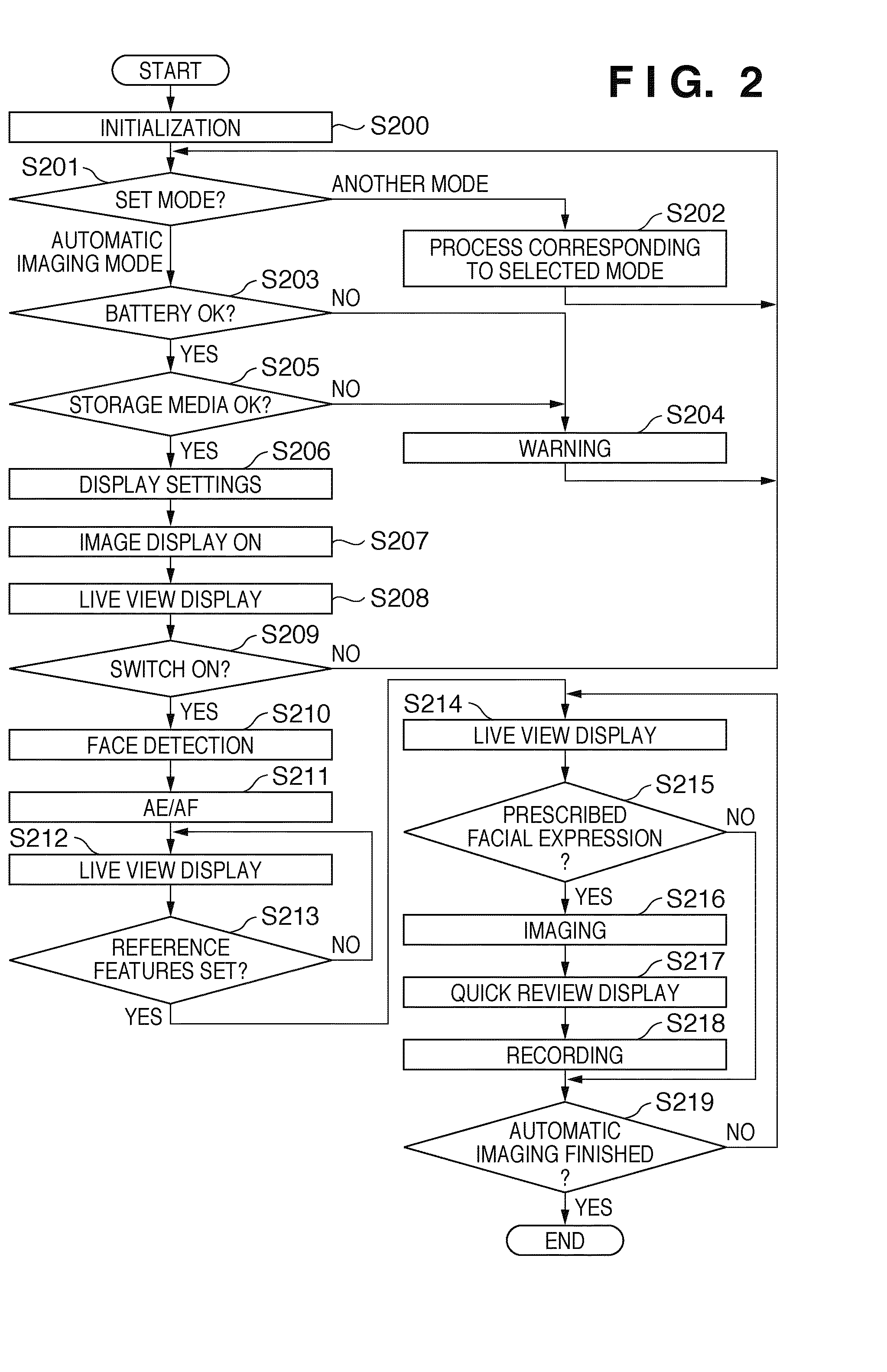
[0128]A second embodiment will be explained next. FIG. 16 is a flow chart illustrating the overall operation of the second embodiment. The explanations below are provided with reference to the flow chart of FIG. 16. The processing performed up to steps S900-S910 is the same as in the first embodiment (steps S200-S210). In addition, the processing performed in steps S915-S920 is also the same as in the first embodiment (steps S214-S219).

[0129]In step S911, the system control circuit 112 performs personal identity authentication for faces detected in step S910. The technology of personal identity authentication is based, for instance, on methods utilizing the mutual subspace technique described in Japanese Patent Laid-Open No. 2000-30065, or methods described in Japanese Patent Laid-Open No. 2003-323622, in which the face region is divided into multiple subregions and comparison is performed for each subregion. In the present embodiment we use the method described in Japanese Patent L...

embodiment 3

[0135]A third embodiment will be explained next. The flow chart describing the overall operation of the embodiment is identical to the one used in the second embodiment (FIG. 16).

[0136]FIG. 19 is a flow chart representing step S914 of FIG. 16, i.e. the reference feature setting process of the third embodiment. Up to step S1000-step S1004 in FIG. 19, the process is identical to the first and second embodiments, namely, steps S300-S304.

[0137]In step S1005, the system control circuit 112 first sets regions for spatial filtering. For instance, the spatial filtering regions are regions 1100, 1101, and 1102 in FIG. 20. These regions are determined with reference to the eye detection positions 400, 401, face detection position 402, and mouth detection position 403. Next, in order to determine whether this is a neutral state, spatial filtering is performed in region 1102 of FIG. 20. The spatial filter used may be, for example, a Sobel filter for horizontal and vertical edge detection, but i...


PUM


Abstract

A facial expression recognition apparatus includes an image input unit configured to sequentially input images, a face detection unit configured to detect faces in images obtained by the image input unit, and a start determination unit configured to determine whether to start facial expression determination based on facial image information detected by the face detection unit. When the start determination unit determines that facial expression determination should be started, an acquisition unit acquires reference feature information based on the facial image information detected by the face detection unit and a facial expression determination unit extracts feature information from the facial image information detected by the face detection unit and determines facial expressions of the detected faces based on the extracted feature information and the reference feature information.

Description

TECHNICAL FIELD[0001]The present invention relates to a facial expression recognition apparatus and method, as well as to an image capturing apparatus, in which facial expressions are recognized based on image information depicting people.BACKGROUND ART[0002]A variety of conventional technologies exist for recognizing facial expressions. In the facial expression recognition described in the specification of Japanese Patent No. 02840816 (hereinafter referred to as Patent Document 1), neutral reference images are prepared in advance for use in the facial expression recognition. The input images and the neutral reference images prepared in advance are then wavelet-transformed to compute the mean power of frequency signals for each band. Facial expressions are then determined by computing the difference between the respective mean powers.[0003]In addition, in the facial expression recognition described in Japanese Patent Laid-Open No. 2005-56388 (hereinafter referred to as Patent Docume...

Claims


Application Information

Patent Timeline
IPC IPC(8): G06K9/46
CPCG06K9/00744H04N5/23219G06K9/00315G06K9/00261G06K9/00248G06V40/167G06V40/165G06V40/176G06V20/46H04N23/611
Inventor KANEDA, YUJIMATSUGU, MASAKAZU
Owner CANON KK
Why Eureka
Try Eureka