Implantable ocular drug delivery device and methods

a technology of ocular drug delivery and implantable ocular structure, which is applied in the direction of prosthesis, drug composition, biocide, etc., to achieve the effects of improving stabilization of device, minimizing distal movement, and improving device stability

Inactive Publication Date: 2010-07-29
SURMODICS INC
View PDF53 Cites 55 Cited by
  • Summary
  • Abstract
  • Description
  • Claims
  • Application Information

AI Technical Summary

Benefits of technology

[0016]Other embodiments of the invention are directed to unique and inventive proximal portion designs that improve, in the least, stabilization of the device, and patient compliance. In these embodiments, the implantable ocular device includes a proximal portion with a cap and / or a transitional portion connecting the coil-shaped body member to the cap. During the insertion process, as the body member becomes fully inserted into the eye by rotation, the distal face of the cap contacts the outer surface of the eye and stabilizes the device in its inserted position.
[0017]Therefore, in another embodiment, the invention provides an ocular drug delivery device having a proximal portion comprising a cap having a distal face with a concave shape. Upon insertion of the device, the distal face of the cap having the concave shape becomes flush with the outer surface of the eye, which is convex. The concave shape of the distal face provides enhanced contact with the outer surface of the eye. With the device in the fully inserted position, the concave shape can improve stabilization of the device and minimize movement of the distal portion in the vitreous.
[0018]In another embodiment, the cap structure has a configuration that improves stabilization of the device by minimizing irritation to the outer eye. In this embodiment, the cap structure has a periphery comprising a rounded cross-sectional shape. The rounded shape reduces irritation to sclera and conjunctiva, which in turn can improve stabilization of the device by minimizing translational movement of device.
[0019]The transitional portion refers to the part of the device between the coil-shaped body member and the cap. The transitional portion is configured to improve the stabilization of the device when inserted in the eye. In particular, when fully inserted in the eye, the transitional portion is in contact with the scleral tissue. In some aspects, the invention provides a device including a transitional portion, which is a linear section that is parallel to the central axis of the device and having a length in the range of about 0.15 mm to about 0.3 mm. Distal to this linear section, the body member curves into the coil shape of the second portion of the coil-shaped body member. The short transitional portion slightly spaces the coil shaped body member away from the distal face of the cap. This spacing improves the placement and stabilization of the device in the eye by wedging scleral tissue into a groove created by the cap, the transitional portion, and the proximal end of the coil-shaped body member.
[0020]The portions of the device that improve stabilization are beneficial as they minimize tissue irritation and can result in the implanted device being more tolerable to a patient during the period of insertion.
[0021]In some embodiments, a primary function of the device is to deliver the bioactive agent(s) to a desired treatment site within the eye. Once the desired treatment of the eye has been accomplished, the device can be removed from the body. Moreover, embodiments of the invention provide a device that is minimally invasive such that risks and disadvantages associated with more invasive surgical techniques can be reduced.

Problems solved by technology

In addition to challenges associated with drug delivery, there are also often challenges associated with the implantation of the device.

Method used


Image

  • Implantable ocular drug delivery device and methods
  • Implantable ocular drug delivery device and methods
  • Implantable ocular drug delivery device and methods

Examples


Embodiment Construction

[0031]The embodiments of the present invention described herein are not intended to be exhaustive or to limit the invention to the precise forms disclosed in the following detailed description. Rather, the embodiments are chosen and described so that others skilled in the art can appreciate and understand the principles and practices of the present invention.

[0032]All publications and patents mentioned herein are hereby incorporated by reference. The publications and patents disclosed herein are provided solely for their disclosure. Nothing herein is to be construed as an admission that the inventors are not entitled to antedate any publication and / or patent, including any publication and / or patent cited herein.

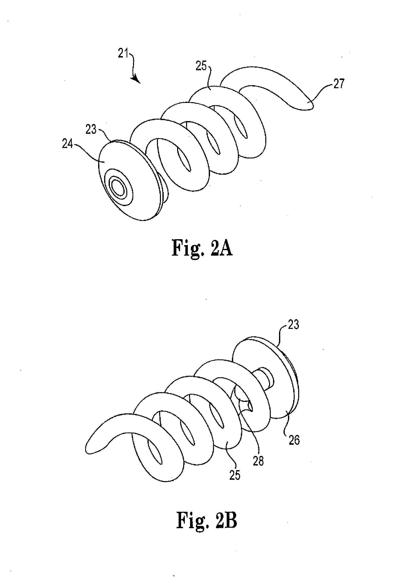
[0033]FIG. 2a shows an illustration of an exemplary implantable ocular device 21 of the present invention, with the proximal end being the closer end in view. The implantable ocular device 21 includes a cap 23, the proximal face 24 of which is shown, a distal portion having a...


PUM


Abstract

The present invention provides implantable ocular drug delivery devices. Generally, the devices have a distal portion with a coil shaped body member and a proximal portion which contacts the sclera. In one aspect, the coil-shaped body member includes a unique configuration including two coiled portions with different pitches, which improves insertion of the device into the eye. In another aspect, the device has a proximal portion that includes a unique cap configuration having a concave distal face that improves stabilization of the device in the eye. In another aspect, the device includes a transitional portion between the cap and the coil-shaped body member that also improves stabilization of the device in the eye. The invention also provides methods for inserting the medical device into the eye, and methods for the treatment of an ocular condition.

Description

CROSS-REFERENCE TO RELATED APPLICATION[0001]The present non-provisional patent application claims priority under 35 U.S.C. §119(e) from U.S. Provisional Patent Application having Ser. No. 61 / 200,294 filed on Nov. 26, 2008, and titled IMPLANTABLE OCULAR DRUG DELIVERY DEVICE AND METHODS, wherein the entirety of said provisional patent application is incorporated herein by reference.FIELD OF THE INVENTION[0002]The invention relates to implantable intraocular medical devices which can be used to deliver bioactive agents to a treatment site in the eye.BACKGROUND OF THE INVENTION[0003]Medical devices can be placed in the body for treatment of a medical condition, such as infection or disease. More recently, technologies have been developed that allow a drug to be released from the device to treat the condition. Some of these technologies involve the release of a drug from a polymeric coating formed on the surface of the device. Other technologies involve the release of the drug from an in...

Claims


Application Information

Patent Timeline
Patent Type & Authority Applications(United States)
IPC IPC(8): A61F2/14A61K31/5575A61P27/02
CPCA61K9/0051A61P27/02
Inventor ERICKSON, SIGNE R.ZHOU, JIANBOPUNJA, KRIPBEELEY, NATHAN R.F.
Owner SURMODICS INC
Why Eureka
Try Eureka