

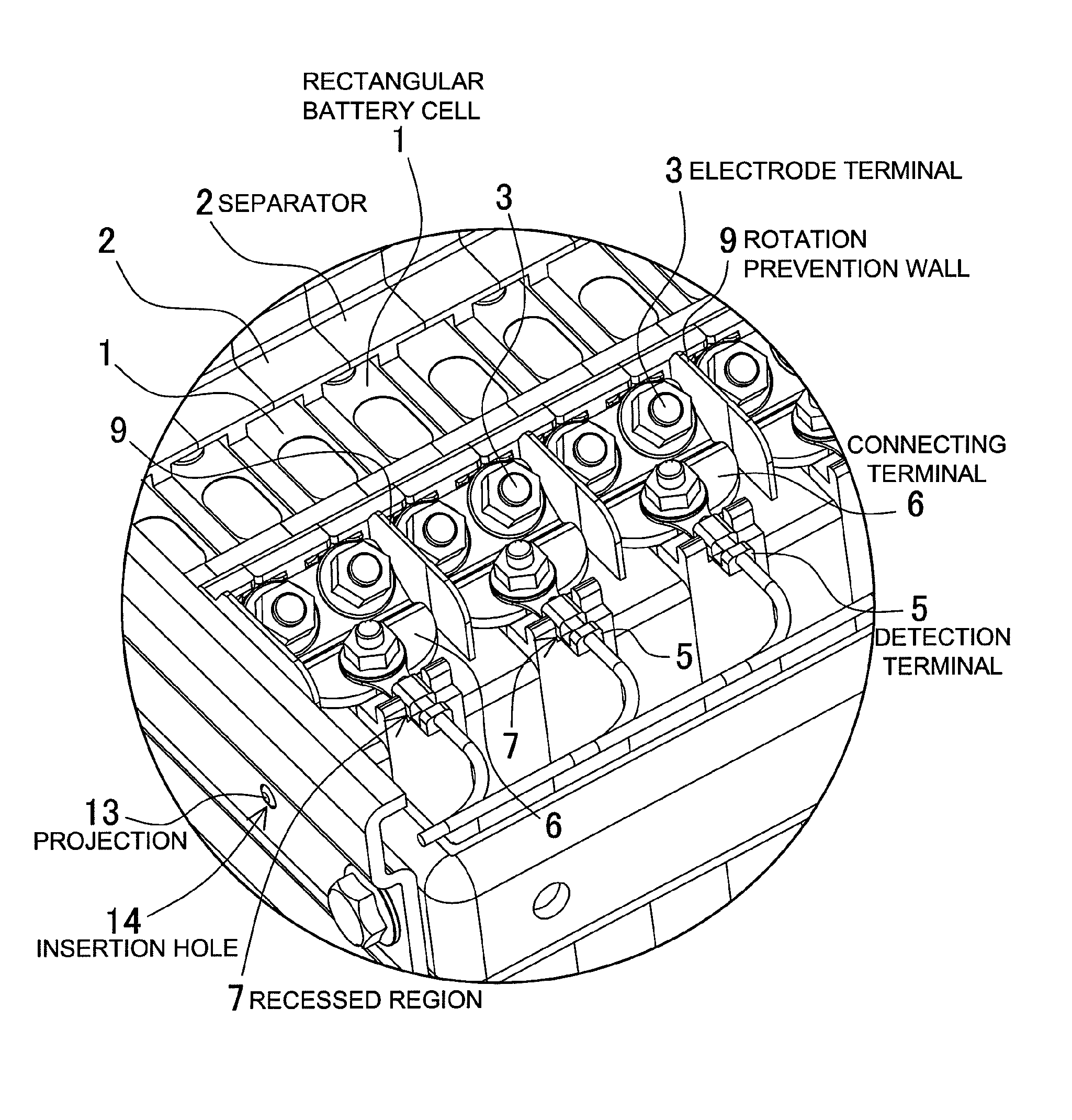
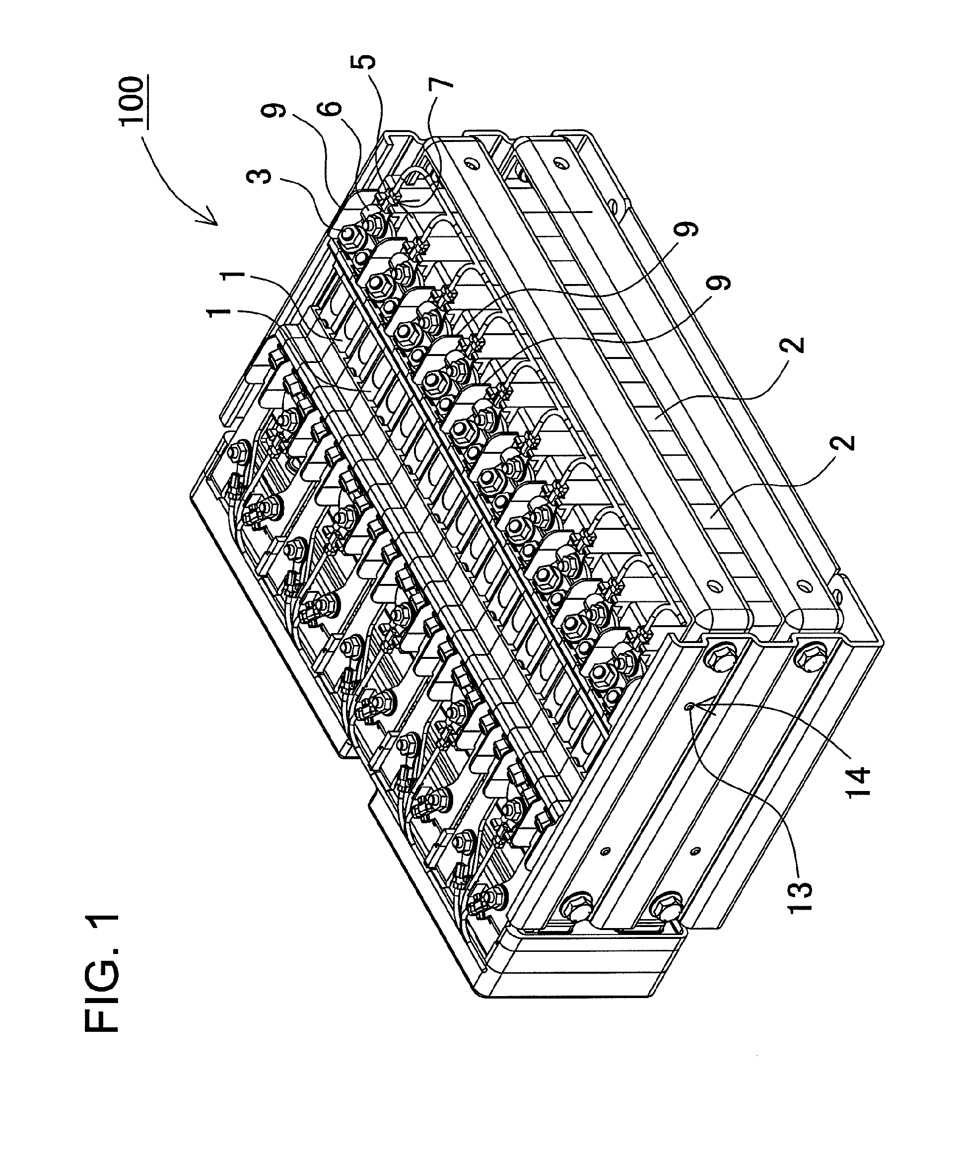
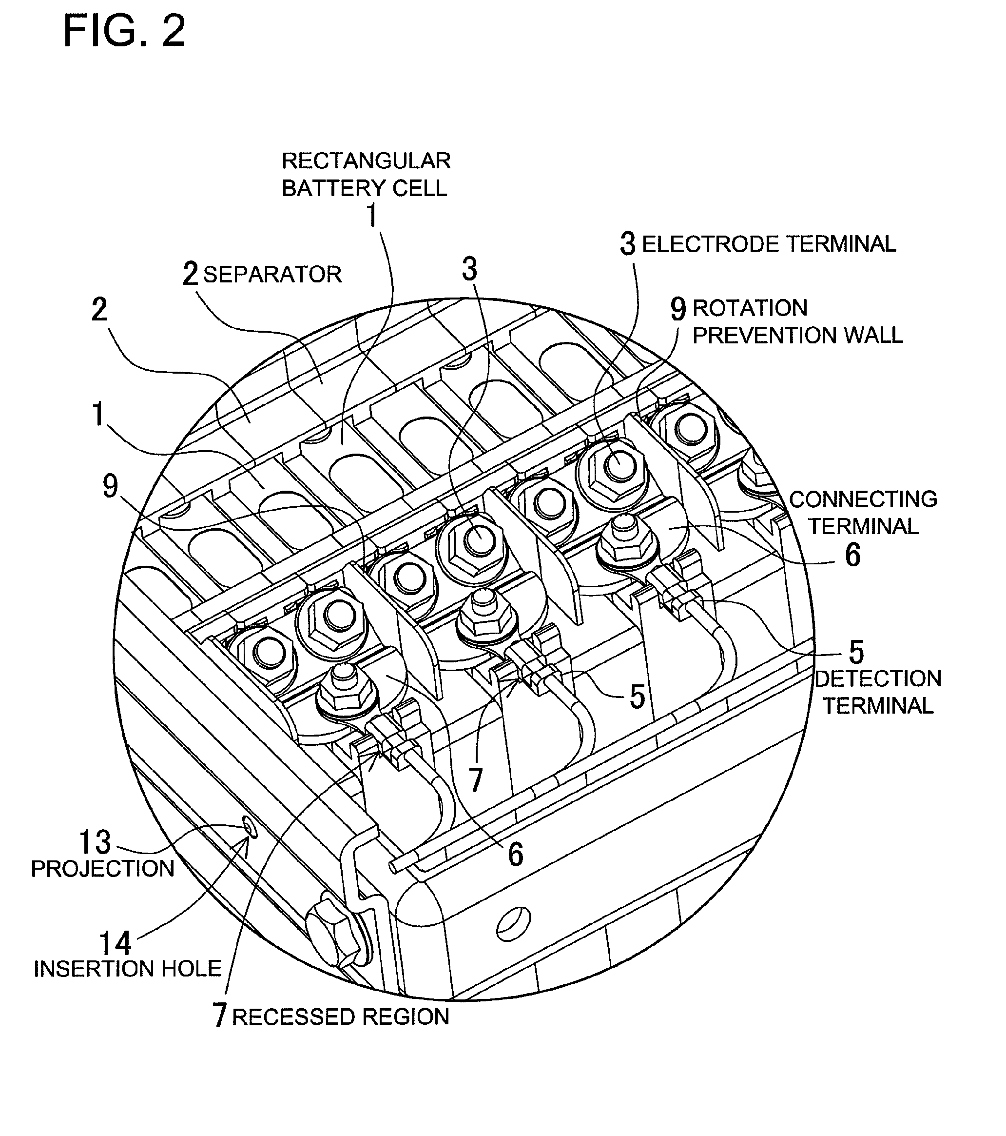
Battery array and battery array separator
a battery array and separator technology, applied in the field of battery arrays, can solve the problems of battery cell structurally fragile parts that can be easily damaged, the upper surface of the battery cell could rotate and deform or rip apart, and the deformation of the connecting terminal 6 or the battery cell is prevented
- Summary
- Abstract
- Description
- Claims
- Application Information
AI Technical Summary
Benefits of technology
Problems solved by technology
Method used
Image

Examples
second embodiment
[0066]FIG. 11 is an oblique view showing the connecting terminals 6 of a battery array for the second embodiment. In this figure, abbreviated illustration shows only one section of rectangular battery cells 1 (four rows on the left side) to make it easy to see the form of the connecting terminals, which are the bus-bars. Here, illustration of the separators 2 is also omitted. In FIG. 11, three types of connecting terminals are used. Second connecting terminals 6B, which are at the center and right side of the figure, are not provided to connect adjacent rectangular battery cells 1, but rather to connect rectangular battery cells 1 that are separated by an interval when the battery cells are in a stacked configuration. Second connecting terminals 6B are made up of horizontal pieces that have inclined surfaces disposed at given intervals in approximately parallel orientation, and connecting vertical pieces that are bent approximately perpendicular to the horizontal pieces.
[0067]A thir...
PUM
| Property | Measurement | Unit |
|---|---|---|
| rotation | aaaaa | aaaaa |
| voltage | aaaaa | aaaaa |
| rectangular shapes | aaaaa | aaaaa |
Abstract
Description
Claims
Application Information