Manufacturing method of airtight container and image displaying apparatus
- Summary
- Abstract
- Description
- Claims
- Application Information
AI Technical Summary
Benefits of technology
Problems solved by technology
Method used
Image
Examples
first embodiment
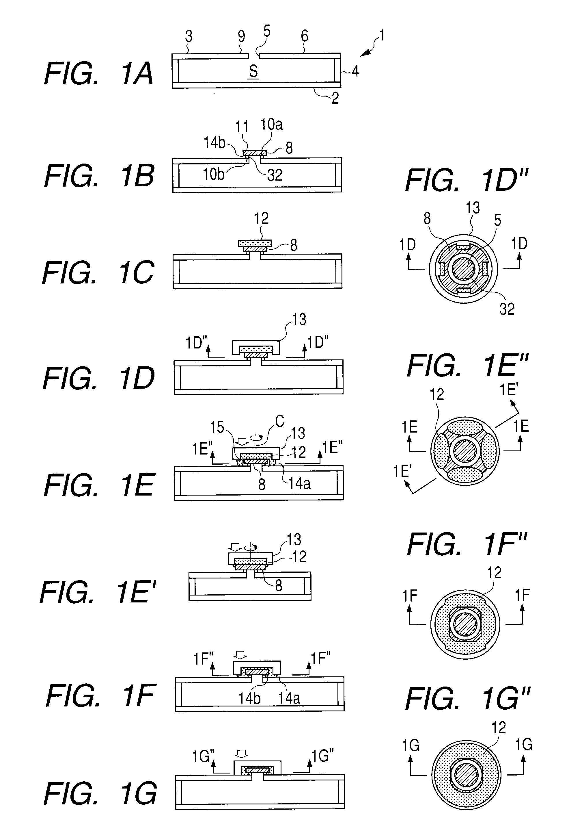
[0027]The first embodiment of the present invention will be described with reference to FIGS. 1A, 1B, 1C, 1D, 1E, 1E′, 1F, 1G, 1D″, 1E″, 1F″ and 1G″. Here, FIGS. 1A, 1B, 10, 1D, 1E, 1E′, 1F, 1G, 1D″, 1E″, 1F″ and 1G″ are the schematic step views indicating a sealing process, which can be particularly preferably used in a case where a through-hole is sealed under a state that the through-hole of an airtight container is placed on an upper surface of an envelope.
[0028]Here, FIGS. 1D″, 1E″, 1F″ and 1G″ are the cross sectional views respectively along the 1D″-1D″ line of FIG. 1D, the 1E″-1E″ line of FIG. 1E, the 1F″-1F″ line and 1G″-1G″ line in FIGS. 1D, 1E, 1F and 1G. Incidentally, FIGS. 1D″, 1E″, 1F″, and 1G″ are the cross sectional views respectively along the 1D″-1D″ line in FIG. 1D, the 1E″-1E″ line in FIG. 1E, the 1F″-1F″ line in FIG. 1F, and the 1G″-1G″ line in FIG. 1G. Further, FIGS. 1D, 1E, 1F, and 1G are the cross sectional views respectively along the 1D-1D line in FIG. 1D″, ...
second embodiment
[0049]The present embodiment is different from the first embodiment in a point that the through-hole is sealed by bringing a laminated body composed of the spacer member 32, the plate member 8a, the sealant 12 and the cover member 13 into contact with the through-hole from the downside of the through-hole, and other points in the present embodiment are the same as those in the first embodiment. Therefore, in the following description, the point different from the first embodiment will be mainly described. Namely, as to the matters not described in the following, the description in the first embodiment should be referred.
[0050]The second embodiment of the present invention will be described with reference to FIGS. 4A, 4B, 4C, 4D, 4D′, 4E, 4C″, 4D″ and 4E″. Here, FIGS. 4A, 4B, 4C, 4D, 4D′, 4E, 4C″, 4D″ and 4E″ are the schematic step views indicating a sealing process which can be especially preferably used in a case where the through-hole is sealed in a state that the through-hole of ...
example 1
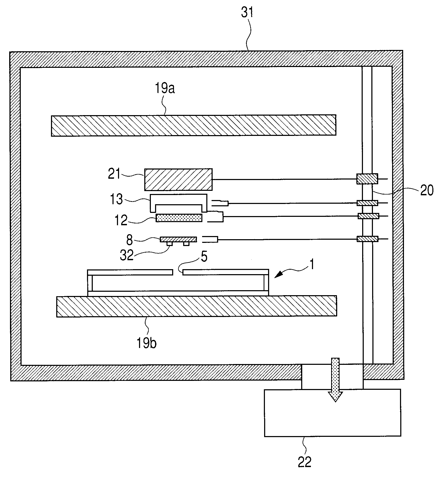
[0065]This is an example of manufacturing an airtight container by using the first embodiment illustrated in FIGS. 1A, 1B, 10, 1D, 1E, 1E′, 1F, 1G, 1D″, 1E″, 1F″ and 1G″. Hereinafter, this example will be described with reference to FIG. 6.
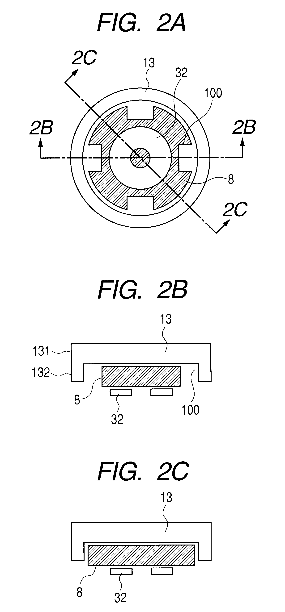
[0066]In this example, the container 1 was stored in a vacuum-exhaust chamber 31, and the vacuum-exhaust chamber 31 was then exhausted to be vacuumized by using an exhaust unit 22 having a turbo molecular pump and a dry scroll pump. Further, heaters 19a and 19b used as heating units were provided in the vacuum-exhaust chamber 31, and the through hole 5 having the diameter of 3 mm was provided on the upper surface of the container 1. The spacer member 32, the plate member 8 and the cover member 13 were illustrated in FIGS. 2A to 2C.
[0067]As the plate member 8, a disk-shaped material of an Fe—Ni alloy having the diameter of 7 mm and the thickness of 0.5 mm was prepared. The four grooves 100 respectively having height and depth of 2 mm were set on th...
PUM
 Abstract
Description
Claims
Application Information
 - R&D
- Intellectual Property
- Life Sciences
- Materials
- Tech Scout
- Unparalleled Data Quality
- Higher Quality Content
- 60% Fewer Hallucinations
Browse by: Latest US Patents, China's latest patents, Technical Efficacy Thesaurus, Application Domain, Technology Topic, Popular Technical Reports.
© 2025 PatSnap. All rights reserved.Legal|Privacy policy|Modern Slavery Act Transparency Statement|Sitemap|About US| Contact US: help@patsnap.com


