Communication Terminal

a terminal and communication technology, applied in the field of communication terminals, can solve problems such as the user's inability to clearly perceive the position of the antenna

Inactive Publication Date: 2010-07-29
KYOCERA CORP
View PDF12 Cites 39 Cited by
  • Summary
  • Abstract
  • Description
  • Claims
  • Application Information

AI Technical Summary

Benefits of technology

[0006]Another object of the present invention is to provide a communication terminal capable of clearly perceiving the position of an antenna.
[0020]According to the fourth invention, the position of the antenna with respect to the display is specified by the position specifier, so that the determiner outputs the determination result on the basis of the specified position of the antenna. In addition, the auxiliary displayer displays the first assist mark or the second assist mark on the display according to the determination result. Accordingly, even if the state of the first case with respect to the second case shifts by the coupler, the position of the antenna with respect to the display can be specified by the position specifier, so that the display displays the first assist mark or the second assist mark. Thus, the user can clearly perceive the position of the antenna irrespective of the state of the first case with respect to the second case.
[0046]According to the present invention, the position of the antenna contained in the communication terminal can be clearly perceived, so that it is possible for the mobile FeliCa chip to surely make Near Field communication with the reader / writer.

Problems solved by technology

Thus, the user could not clearly perceive the position of the antenna when the mobile FeliCa chip contained in the communication terminal makes Near Field communication with the reader / writer.

Method used


Image

  • Communication Terminal
  • Communication Terminal
  • Communication Terminal

Examples


first embodiment

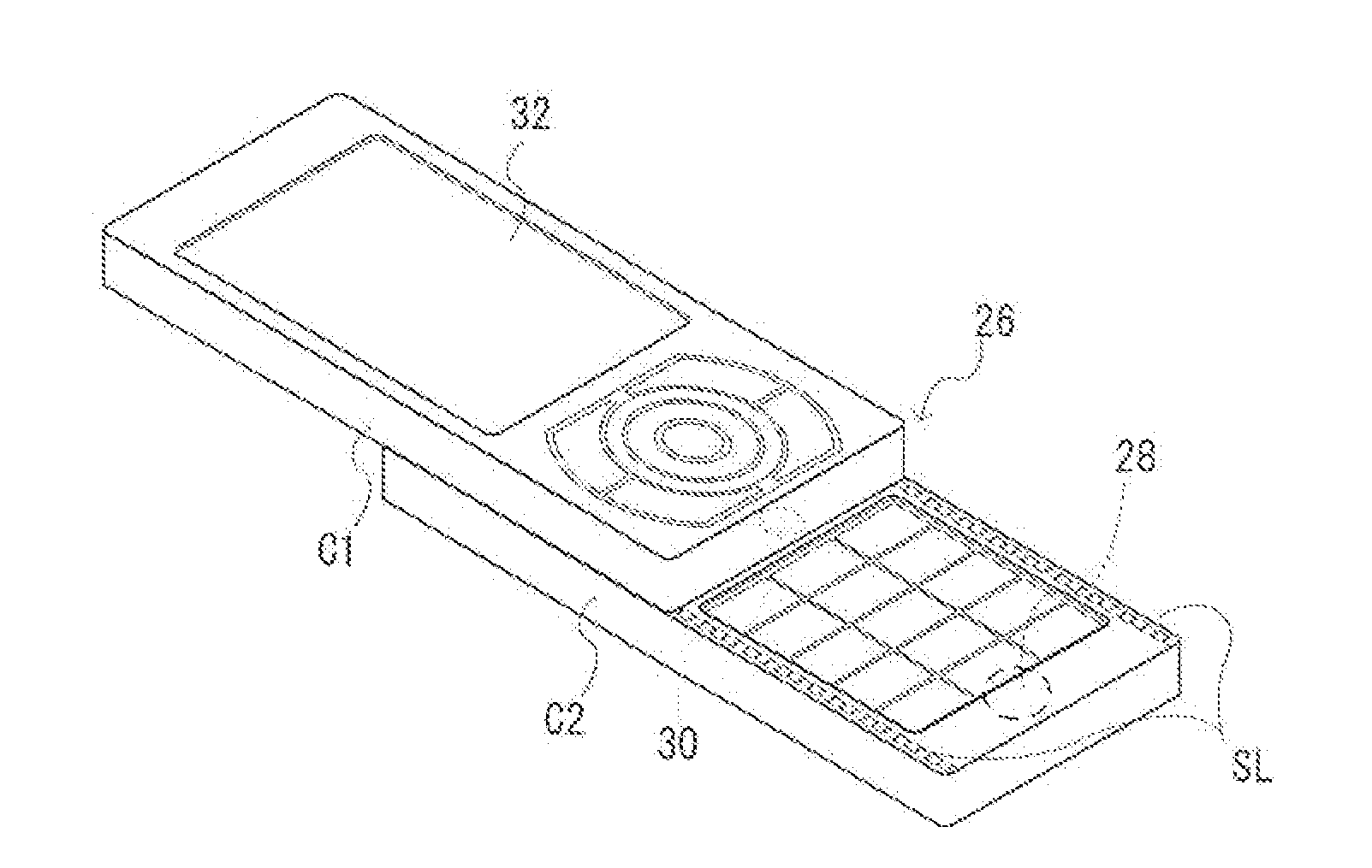
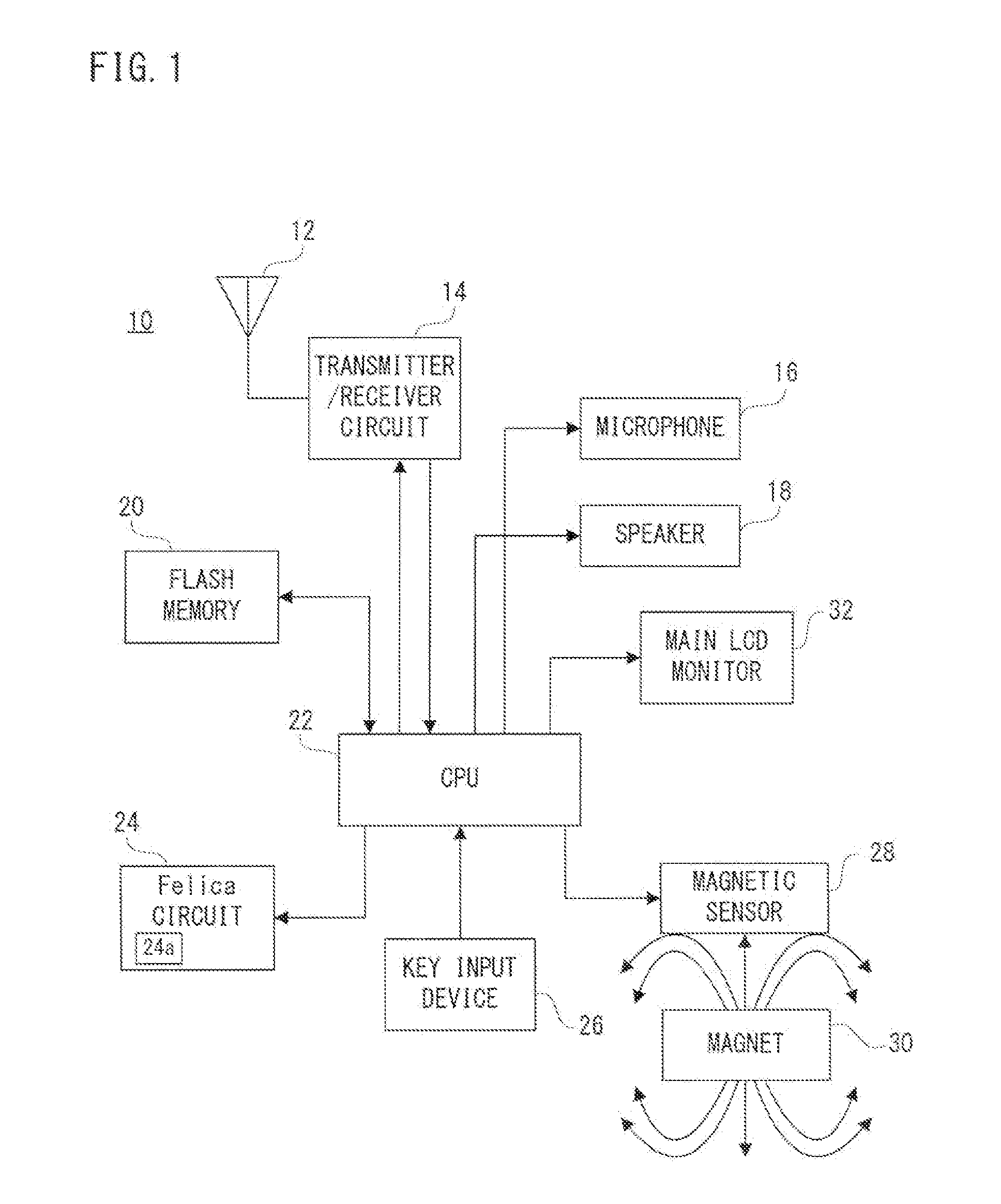
[0068]Referring to FIG. 1, a mobile communication terminal 10 of a first embodiment includes a key input device 26. When a call-out operation is performed with the key input device 26, the CPU 22 controls a transmitter / receiver circuit 14 corresponding to a CDMA system to output a call-out signal. The output call-out signal is emitted from the antenna 12, and sent to a telephone of an intended party through a mobile communication network including base stations. When the intended party performs a call-in operation, a telephone-communication-allowable state is established.

[0069]When a conversation end operation is performed with the key input device 26 after shift to the telephone-communication-allowable state, the CPU 22 controls the transmitter / receiver circuit 14 to send a conversation end signal to the intended party. After sending the conversation end signal, the CPU 22 ends the conversation processing. In a case that a conversation end signal sent first from the intended party ...

second embodiment

[0099]In the second embodiment, the rotating mechanism K is adopted to be of configuration as shown in FIG. 1 in place of the sliding mechanism SL. Furthermore, the second embodiment is the same as the first embodiment in the configuration of the mobile communication terminal in FIG. 1 and the processing of Felica mode controlling task in FIG. 4 which are used for the explanation of the first embodiment, and therefore, in the description of the second embodiment, these drawings and the explanations are omitted.

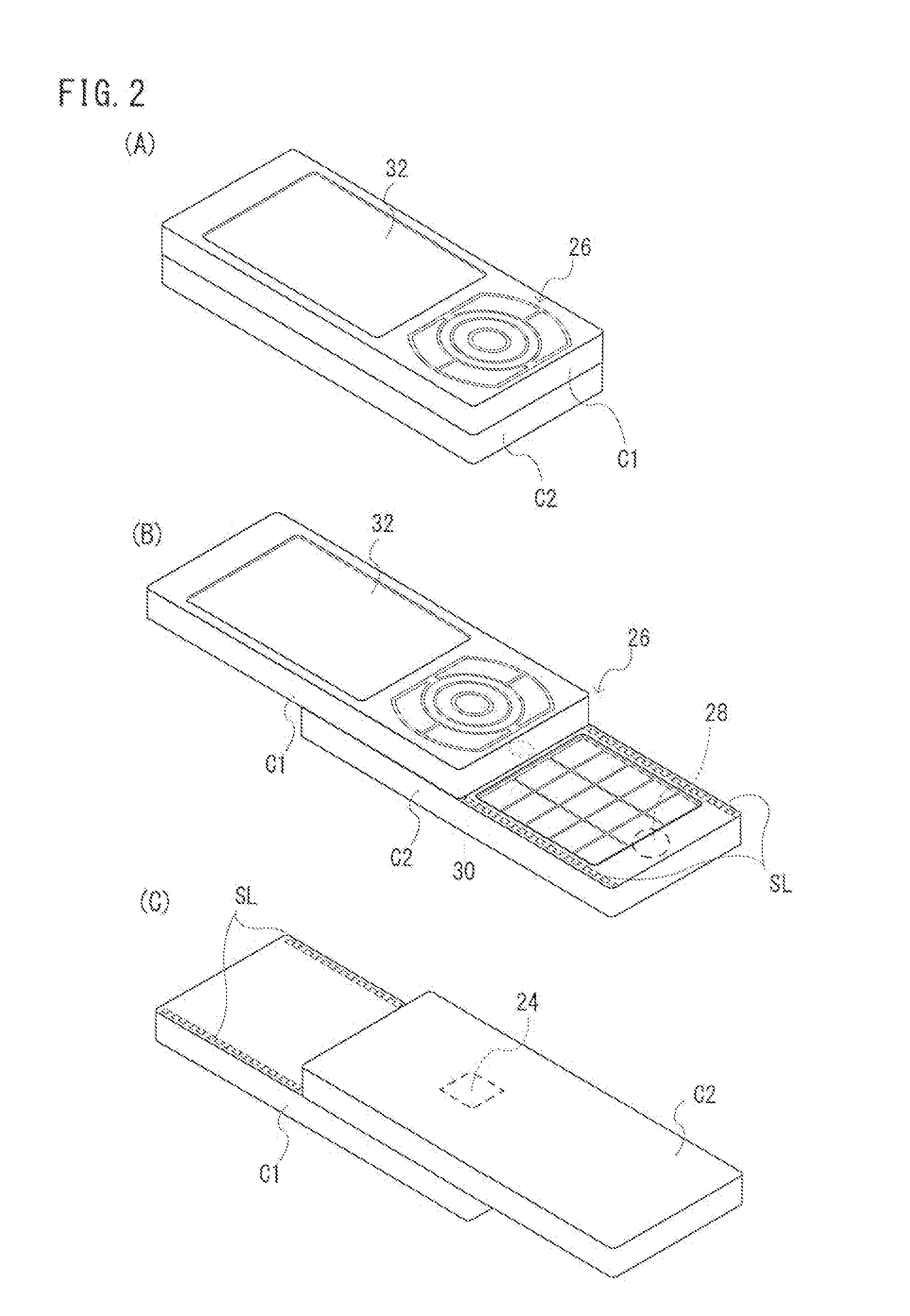
[0100]Referring to FIG. 6(A)-FIG. 6(D), the Felica circuit 24 is contained in a case C2 such that an antenna 24a retains good receiving sensitivity on a bottom surface of the case C2. A key input device 26 is attached to the case C2 such that the operation keys are exposed from the top surface of the case C2. A magnetic sensor 28 is contained in the case C2. The magnet 30 is contained in a case C1 so as to be closest to the magnetic sensor 28 in states of FIG. 6(A) and FIG. 6(...

third embodiment

[0116]In a third embodiment, a hinge mechanism H1 or a hinge mechanism H2 is adopted in a configuration shown in FIG. 7 in place of the sliding mechanism SL. Furthermore, the third embodiment is the same as that of the Felica mode controlling task in FIG. 4 used in the explanation of the first embodiment, so that the explanation of FIG. 4 is omitted in the explanation of the third embodiment.

[0117]Referring to FIG. 7, the mobile communication terminal 10 of the third embodiment has a sub LCD monitor 34 in addition to the mobile communication terminal 10 of the first embodiment.

[0118]Referring to FIG. 8(A)-FIG. 8(C), FIG. 9(A)-FIG. 9(C) and FIG. 10, in FIG. 8(A)-FIG. 8(C), the Felica circuit 24 is contained in a case C1 such that the antenna 24a retains good receiving sensitivity on an outer surface of the case C1. In FIG. 9(A)-FIG. 9(C), the Felica circuit 24 is contained in the case C2 such that the antenna 24a retains good receiving sensitivity on the outer surface of the case C2....


PUM


Abstract

Each of the cases C1 and C2 is formed in a plate. A sliding mechanism SL1 is slidably coupled with the case C1 and the case C2. A Felica circuit 24 is provided with an antenna (24a), and is contained in the case C2. A magnetic sensor 28 is contained in the case C2. A magnet 30 is contained in the case C1. A main LCD monitor 32 is attached to a top surface of the case C1. A CPU (22) determines whether an open position or a closed position from the output value of the magnetic sensor 28. In the closed position, an assist mark (36) is displayed on the main LCD monitor 32 at a position of the antenna (24a) with respect to the main LCD monitor 32.

Description

CROSS REFERENCE TO RELATED APPLICATIONS[0001]This application is the U.S. National Stage application of PCT application PCT / JP2008 / 063927 filed on Jul. 28, 2008, which claims priority under 35 U.S.C. §119 to Japanese Patent Application No. 2007-197013 filed on Jul. 30, 2007, and the contents of each of these applications are incorporated herein by reference in their entirety.FIELD OF THE INVENTION[0002]The present invention relates to a communication terminal. More specifically, the present invention relates to a communication terminal which performs communications by utilizing an antenna for Near Field Communication.BACKGROUND[0003]One example of an apparatus of such a kind is disclosed in an instruction manual of W51SA by SANYO on page 274-278 opened on Feb. 9, 2007 (non-patent document 1), for example. According to the prior art, a communication terminal containing a mobile FeliCa chip configured on the basis of a technique of a contactless IC card called “FeliCa” (registered tra...

Claims


Application Information

Patent Timeline
Patent Type & Authority Applications(United States)
IPC IPC(8): H04M1/00
CPCH01Q1/2216H01Q1/243H04M1/0245H04M1/0235H04M1/021
Inventor FUJII, KATSUSHIGE
Owner KYOCERA CORP
Why Eureka
Try Eureka