
Biodegradable stent graft

a biodegradable, stent technology, applied in the field of tissue reconstruction, can solve the problems of weakened ability to dilate and constrict the wall of the vessel, damage to the vessel wall, and affecting the healing effect of the stent,

Inactive Publication Date: 2010-07-29
COX MITCHELL WAYNE
View PDF6 Cites 23 Cited by
  • Summary
  • Abstract
  • Description
  • Claims
  • Application Information

AI Technical Summary

Problems solved by technology

A vessel wall may be damaged in many ways including chronic wear and weakening of the tissue that may eventually lead to weakened ability to dilate and constrict the wall of the vessel (e.g., aneurysm, artherosclerosis, angina, stroke, and other common types of ischemia).
Vessels may also suffer acute trauma-related injuries such as from gunshot wounds, puncturing, bruising, or otherwise damaging the vessel wall by an object.
Oftentimes, vessel damage leads to serious medical conditions and may result in long-term injury or even death of a patient.
When a vessel wall ruptures, gets punctured, cut, or otherwise damaged, blood may leak through the damaged portion of the vessel into the surrounding tissue causing significant damage.
Such an injury causes blood pressure through the damaged portion of the vessel to drop and may prevent oxygenated blood from reaching a particular organ or other tissue destination or deoxygenated blood from reaching the lungs.
Oftentimes, stents that are permanently implanted within a vessel cause complications over a length of time.
This can be especially problematic with some young patients.
In addition to the stent gradually blocking up the vessel, it is also possible that the stent can also fracture.
However, during this procedure, the endograft remains in place for life commonly requiring lifetime follow up to the site.

Method used


Image

  • Biodegradable stent graft
  • Biodegradable stent graft
  • Biodegradable stent graft

Examples


first embodiment

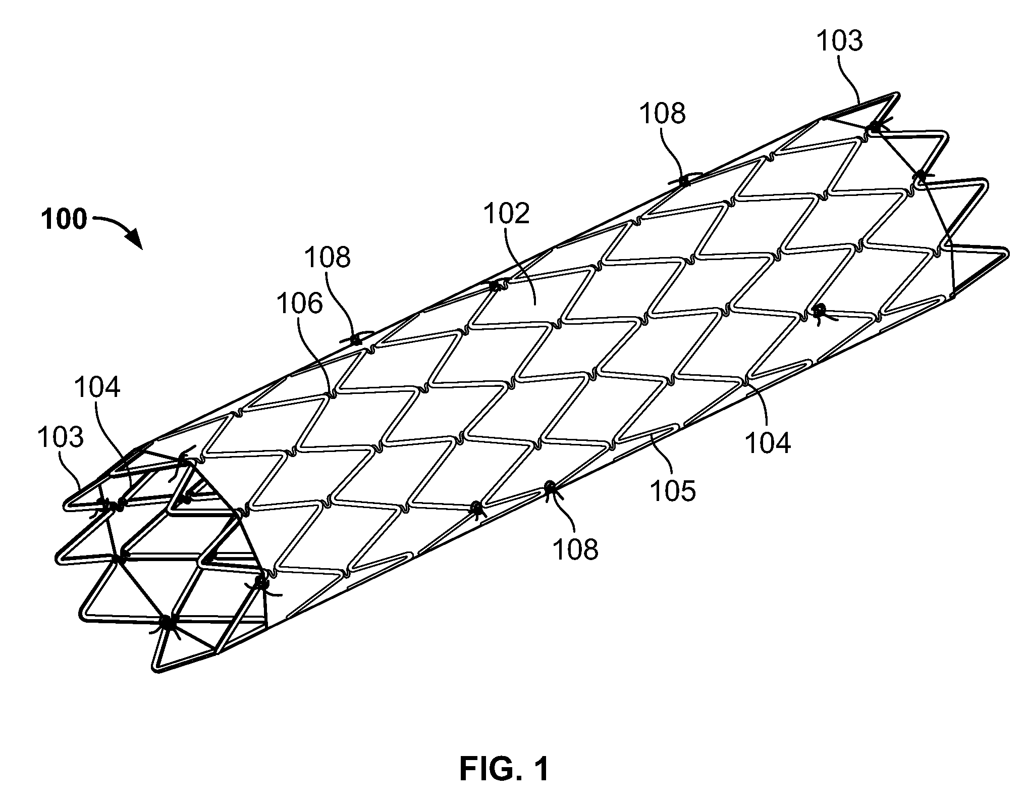
[0023]In a first embodiment, the outer surface of the sheet 102 is adhesive free and the vessel wall will grow into it aided by the force applied to it from the frame 104 once deployed. The sheet 102, and more specifically the outer surface of the sheet 102, may include seeding cells (not shown) coupled to it. The seeding cells may be endothelial cells or stem cells from the patient or a matching donor. The seeding cells help promote cell ingrowth from the inner vessel wall to the sheet 102.

third embodiment

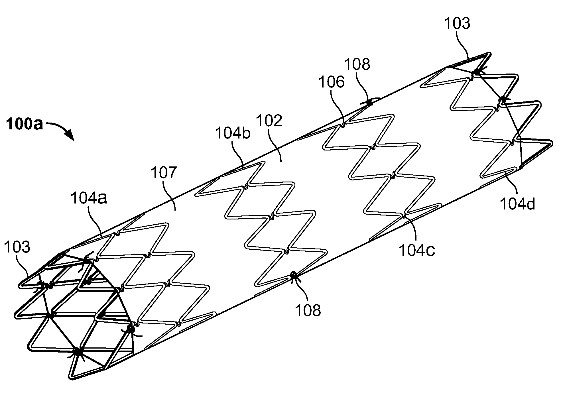
[0024]The sheet 102 is attached to the frame 104 in any desirable manner. In a first arrangement, the sheet 102 is sewn to the frame 104 at selected points along the length and circumference of the frame 104 based on the design of the frame 104. Element 108 depicts sewing points 108 between the sheet 102 and the frame 104. Alternatively, or in addition, the sheet 102 may be joined to the frame 104 by suitable body-compatible adhesives such as fibrin glue. In a third embodiment, not shown, the stent graft has a sheet inside the frame in addition to the outer sheet 102. The inner and outer sheets are compressed or are heat sealed with the frame 104 therebetween.

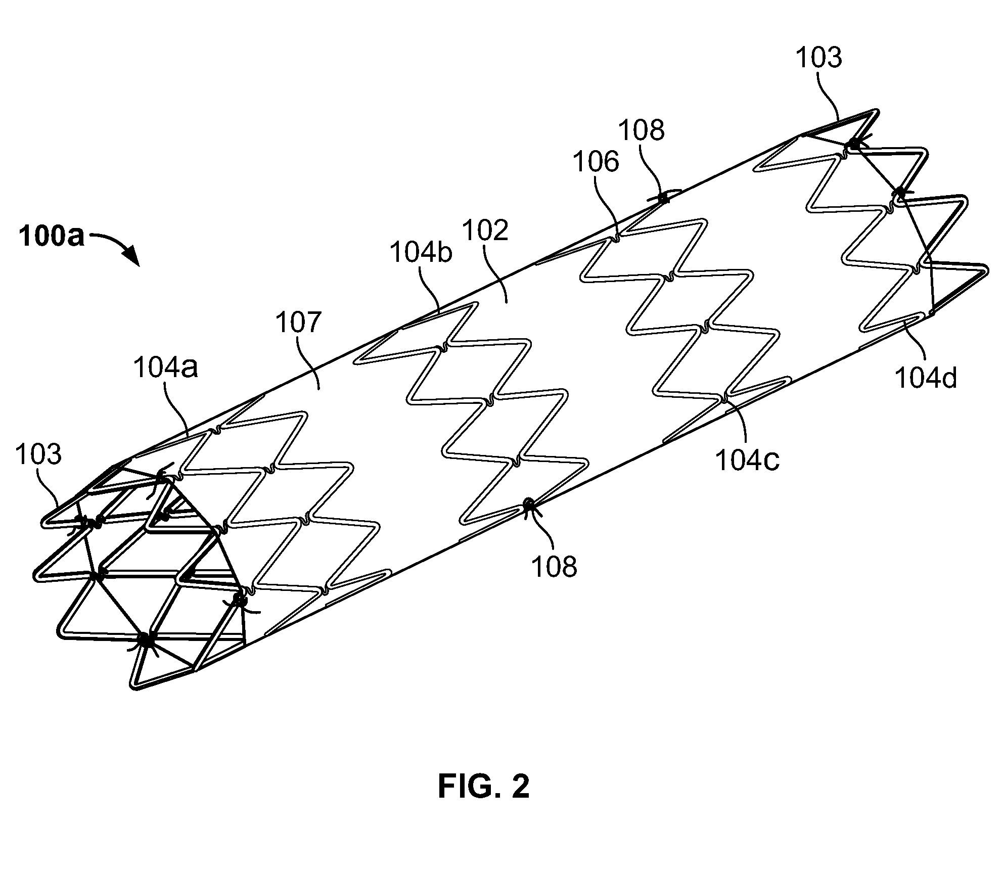
[0025]FIG. 2 depicts an alternative embodiment to FIG. 1. More specifically, the embodiment of FIG. 2 differs from that of FIG. 1, in that the frame is not a unitary element. Rather, the frame is constructed of at least two longitudinally spaced independent frame sections. In the depicted embodiment of FIG. 2, the frame is form...


PUM

PropertyMeasurementUnit
timeaaaaaaaaaa
timeaaaaaaaaaa
timeaaaaaaaaaa

Abstract

A stent may help to reconstruct tissue in a vessel by causing the tissue to re-epithelialize. The stent may include a biodegradable frame and a sheet that coats the frame. The sheet may contain a biological material and may flex in unison with the frame in a radial direction. When placed in a vessel, the stent may at least partially conform to at least a portion of a vessel wall. The stent may be capable of being absorbed over a period of time, such as five years, one year, or six months. The stent may flex as the vessel wall dilates and constricts. The stent may be placed in any type of vessel including an artery and mobile vessels. The biodegradable frame may be made of a poly-lactide and / or magnesium. The sheet may contain a biological material including biologic arterial graft and / or an acellular dermal matrix.

Description

BACKGROUND OF THE INVENTION[0001]1. Field of the Invention[0002]The present invention relates to a device for tissue reconstruction. The invention concerns, more particularly, a biodegradable stent having a sheet containing a biological material that is used to reconstruct tissue in blood vessels.[0003]2. Description of Background Art[0004]A vessel wall may be damaged in many ways including chronic wear and weakening of the tissue that may eventually lead to weakened ability to dilate and constrict the wall of the vessel (e.g., aneurysm, artherosclerosis, angina, stroke, and other common types of ischemia). Stents are commonly used for repairing vessel walls in patients suffering from chronic and acute vessel tissue injuries. Vessels may also suffer acute trauma-related injuries such as from gunshot wounds, puncturing, bruising, or otherwise damaging the vessel wall by an object. Oftentimes, vessel damage leads to serious medical conditions and may result in long-term injury or even...

Claims


Application Information

Patent Timeline
Patent Type & Authority Applications(United States)
IPC IPC(8): A61F2/06A61F2/82
CPCA61F2/07A61F2/915A61F2002/826A61F2002/91558A61F2230/0054A61F2/90A61F2220/005A61F2220/0075A61F2210/0004
Inventor COX, MITCHELL WAYNE
Owner COX MITCHELL WAYNE
Learn More