Sawyer-singleton geothermal energy tank

a geothermal energy tank and solitary technology, applied in indirect heat exchangers, greenhouse gas reduction, lighting and heating apparatus, etc., can solve the problems of not being able to use dense urban areas, the water body must be 34 of an acre, and the method cannot be used in dense urban areas

Inactive Publication Date: 2010-08-05
SINGLETON JR CALVIN MONROE +1
View PDF13 Cites 13 Cited by
  • Summary
  • Abstract
  • Description
  • Claims
  • Application Information

AI Technical Summary

Problems solved by technology

Our embodiment does not address the indoor, mechanical portion of the system.
The drawback for this system is that the body of water must be ¾ of an acre for each ton of cooling needed.
Few people in rural areas have access to a body of water of this size.
It is also safe to say that this method cannot be used in dense urban areas.
It, however, cannot be used in urban areas where the entire lot may only be 45 ft. by 145 ft.
This method is expensive, costing from $1,500.00 to $2,000.00 per drill hole.
As with the two previous methods, a lot of space is required.
This method is limited to rural and commercial uses where the cost of space is not at...

Method used


Image

  • Sawyer-singleton geothermal energy tank
  • Sawyer-singleton geothermal energy tank
  • Sawyer-singleton geothermal energy tank

Examples


first embodiment

—FIRST EMBODIMENT

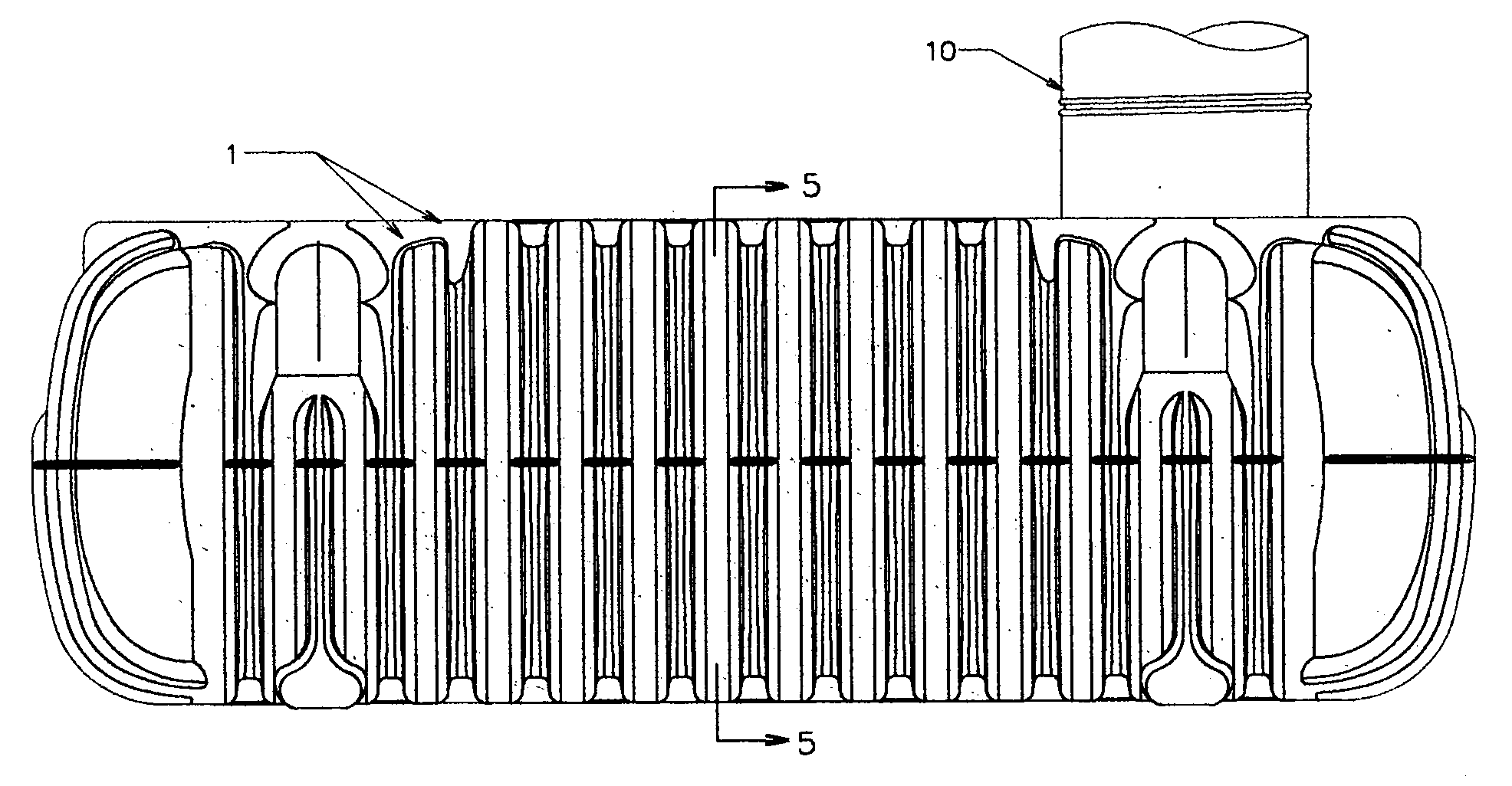
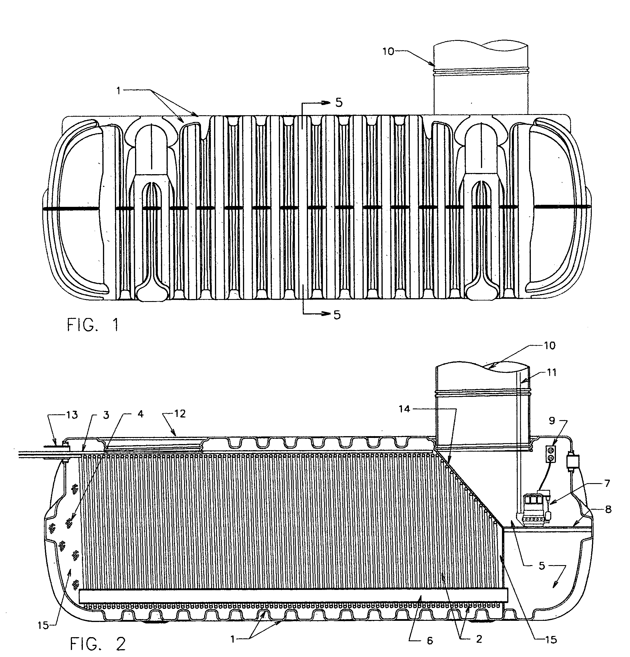
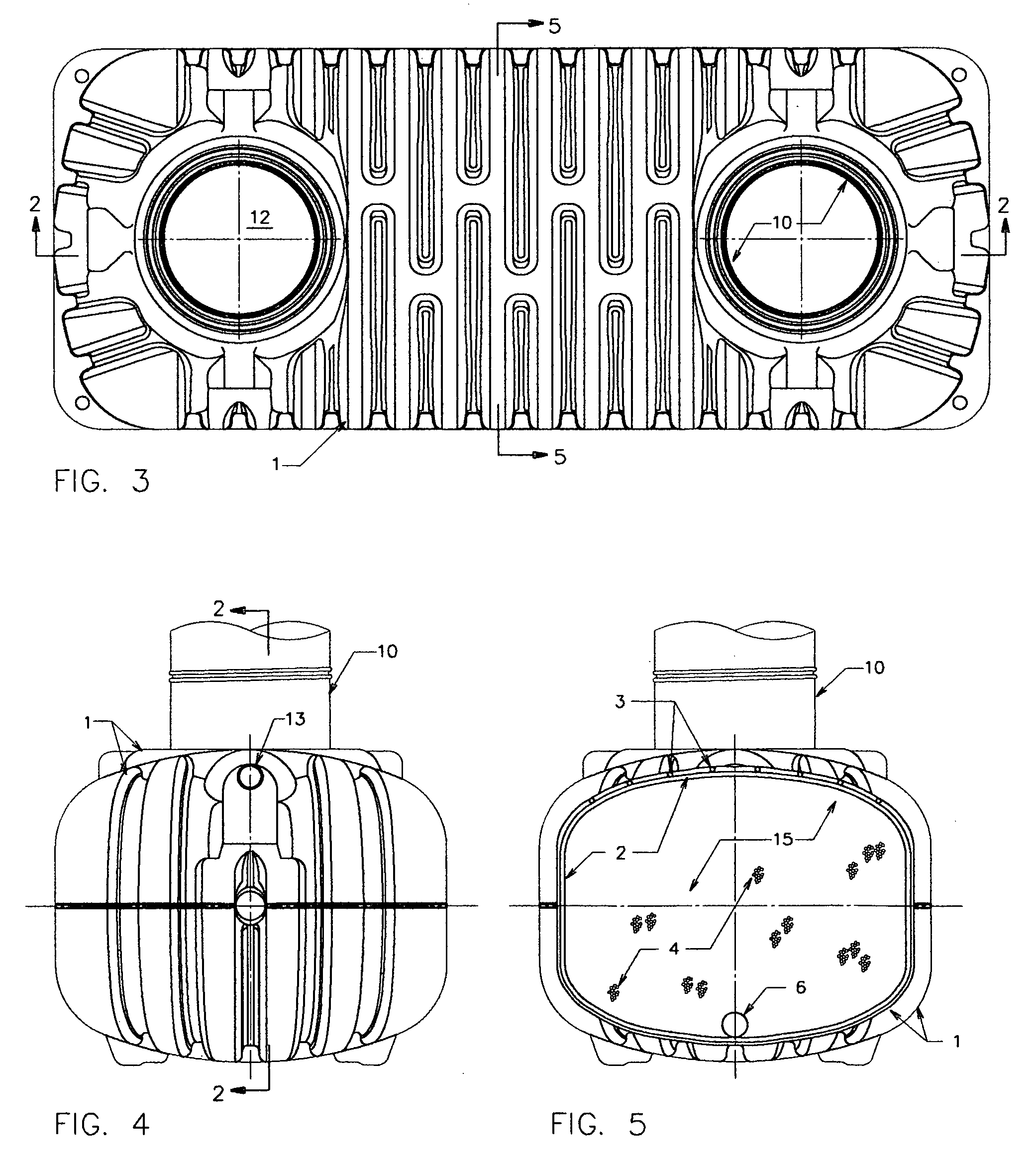
[0050]Referring to Sheets 1 / 2 and 2 / 2, the first embodiment of the closed loop geothermal energy exchange tank comprises a rectangular structure (1) capable of being buried within the earths' geothermal zone without failure. Attached to the interior walls of the structure is a continuous coil of 11 / 16″ diameter plastic tubing spaced ½ inches apart (2). In contact with the plastic tubing is a mass of permeable soil (4), filling the interior of the energy exchange chamber. If needed, water is introduced to the interior soil mass by ¾″ diameter perforated plastic pipes (3), which pass through a conduit sleeve (13) and runs the length of an energy exchange chamber (15) containing the plastic tubing.

[0051]The water is used to regulate the temperature of the interior soil mass when needed. The interior soil mass, in turn, removes the heat from the cooling fluid flowing within a continuous coil of plastic tubing (2) that forms a closed loop with the heat pump.

[0052]After i...

embodiment # 1

Alternate Embodiment #1

[0055]The interior soil mass referenced in FIGS. 2 and 5 of the first embodiment is partially replaced by a light weight structure, such as Styrofoam, to reduce both the weight of the containment tank and limit the work required on site to install the interior soil mass. This light weight structure will be located at or near the center of the tank and will allow a reduced thickness of the interior soil mass to be in contact with the coils located on the interior wall of the containment tank.

embodiment # 2

Alternate Embodiment #2

[0056]The interior soil mass referenced in FIGS. 2 and 5 is partially replaced by a smaller interior tank of the same shape as the original tank. This interior tank would be located such that a reduced thickness of the interior soil mass will remain in contact with the coils located on the interior walls the containment tank. The internal tank will serve several purposes. The first being to reduce weight and jobsite labor by reducing the amount of interior soil mass required. Secondly, the interior tank will serve as the water overflow chamber, thus reducing the overall length of the containment tank and eliminating the perforated drain pipe.

[0057]The bottom of the interior tank would be perforated, allowing water to, under hydrostatic pressure, fill the interior tank. The sump pump, the pump platform, the water discharge pipe, the power source and the manhole extension section, would be incorporated into the interior tank.


PUM


Abstract

One embodiment of a compact, closed loop geothermal energy exchange system, which is used in conjunction with geothermal heat pumps to heat and cool interior spaces, is provided. Conduit (2), through which process fluid flows, is configured within a containment tank (1) in a manner that optimizes the contact between the conduit, an interior soil mass (4) and the soil mass exterior to the tank. Water from a source within the geothermal zone of the earth is introduced, when necessary, to the interior of the tank by means of a temperature regulated valve (not shown) and pipes (3) located at the top of the tank. The interior soil mass, the exterior soil mass and the water, in combination, will regulate the temperature of the process fluid, thereby providing optimum operating fluid temperatures for geothermal heat pumps. A means of collecting the water and removing it from the tank is provided by a perforated pipe (6) connected to a water overflow chamber (5). The collected water is removed from the overflow chamber by a sump pump (7), and a discharge pipe (11).

Description

CROSS-REFERENCE TO RELATED APPLICATIONS[0001]Provisional Application Filed[0002]Dec. 18, 2007[0003]Application No. 61 / 007,952STATEMENT REGARDING FEDERALLY SPONSORED RESEARCH OR DEVELOPMENT[0004]“Not Applicable”REFERENCE TO SEQUENCE LISTING, A TABLE, OR A COMPUTER PROGRAM LISTING COMPACT DISC APPENDIX[0005]“Not Applicable”BACKGROUND[0006]1. Field[0007]This application relates to the use of the earths geothermal energy to heat and cool residential and commercial structures with a closed loop geothermal heat exchanger, which makes use of both soil mass and water to regulate the temperature of the fluid used by geothermal heat pumps.[0008]2. Prior Art[0009]Geothermal energy in the context of this embodiment refers to that constant temperature of the earth that exists at a level close to the surface of the earth. That level varies somewhat from one geographical region to another but is generally agreed to be below frost level.[0010]This constant temperature is now being tapped to heat an...

Claims


Application Information

Patent Timeline
IPC IPC(8): F24J3/08
CPCF24J3/081F28D20/0052Y02E70/30Y02E60/142Y02E10/12F24T10/10F24T10/30Y02E10/10Y02E60/14
Inventor SINGLETON, JR., CALVIN MONROESAWYER, JAMES MARVIN
Owner SINGLETON JR CALVIN MONROE
Why Eureka
Try Eureka