Rotary evaporator

a rotary evaporator and evaporator technology, applied in mechanical equipment, distillation separation, distillation, etc., can solve the problem that the seal has only a limited operating life, and achieve the effect of increasing the operating life of the seal

Active Publication Date: 2010-08-05
HANS HEIDOLPH
View PDF21 Cites 18 Cited by
  • Summary
  • Abstract
  • Description
  • Claims
  • Application Information

AI Technical Summary

Benefits of technology

[0007]It is the underlying object of the invention to provide...

Problems solved by technology

Such a seal has, however,...

Method used


Image

  • Rotary evaporator
  • Rotary evaporator
  • Rotary evaporator

Examples


Embodiment Construction

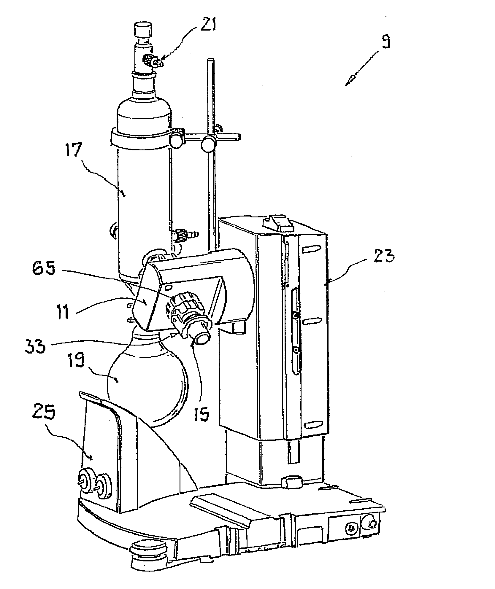
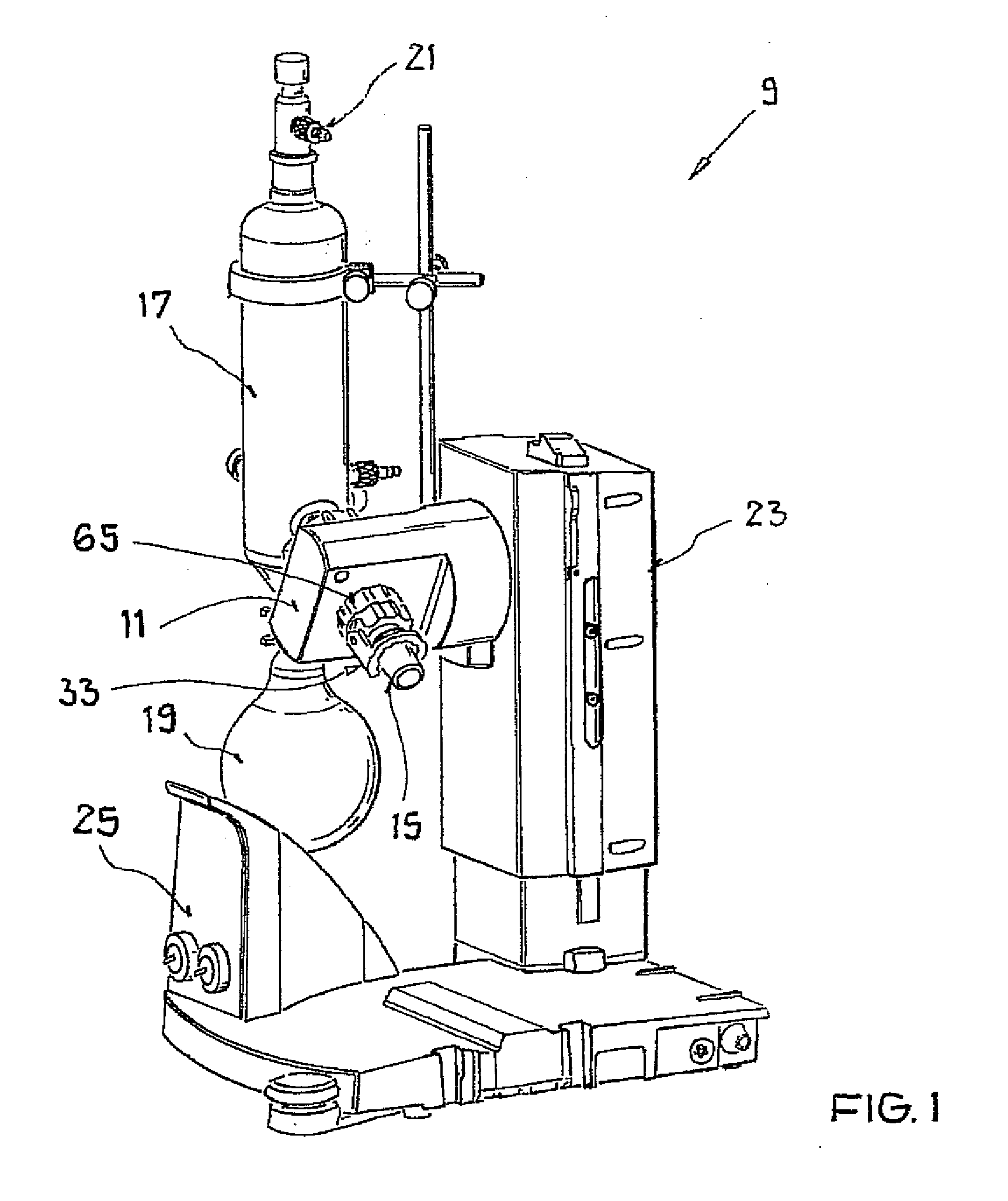
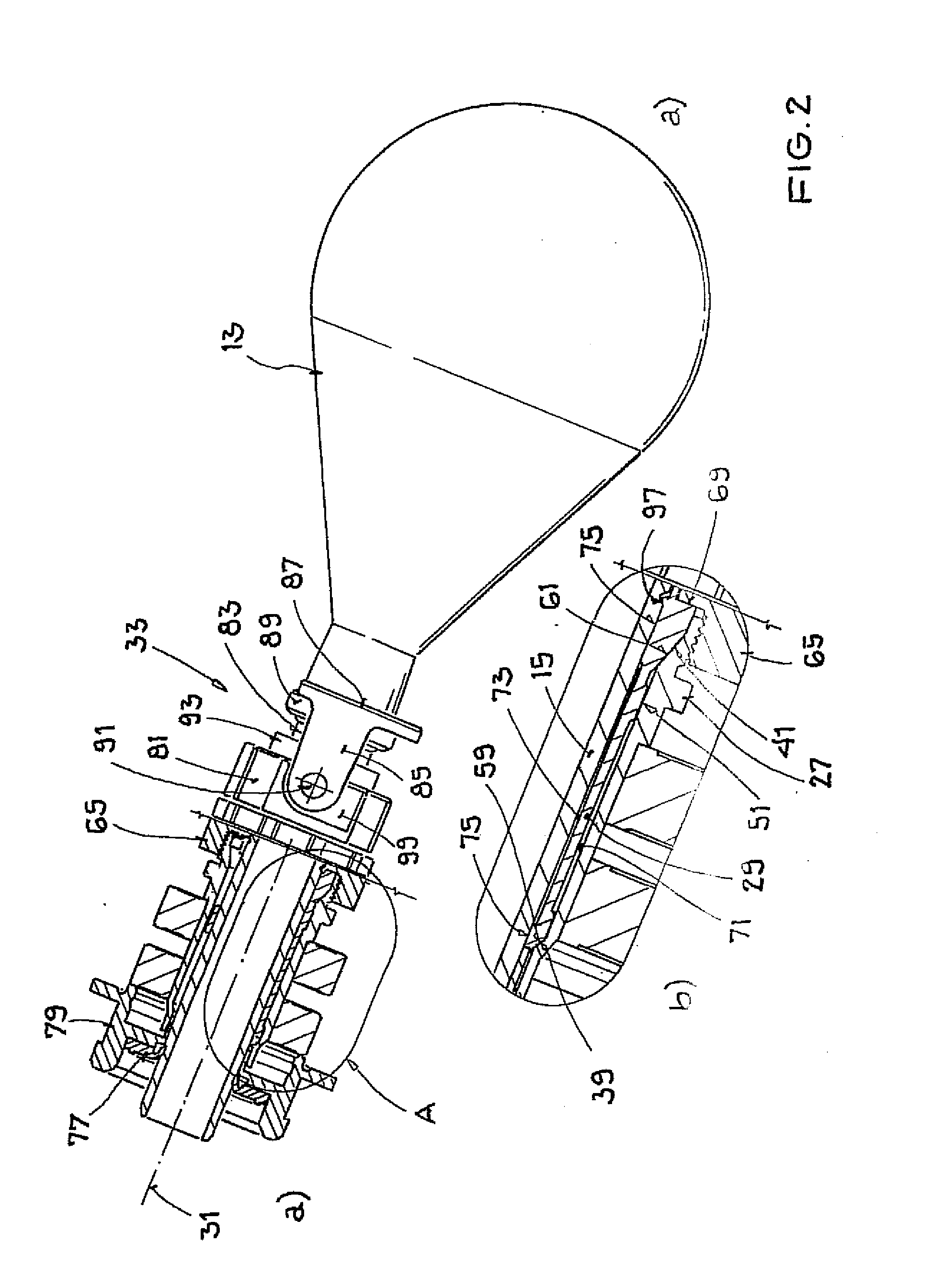
[0039]The rotary evaporator 9 shown in FIG. 1 includes a rotary drive 11 for an evaporator flask 13, in particular of glass, which is shown only in FIG. 2 and is designed as a round bottomed flask or a V-shaped flask or the like and which can be heated in a heating bath, not shown, to evaporate distillate from a liquid mixture present therein. The evaporated distillate then moves via a steam leadthrough 15 formed as a hollow glass shaft which is guided through the rotary drive 11 and of which only a ground core projecting obliquely downwardly from the rotary drive 11 can be recognized in FIG. 1 into a cooler 17 to condensate there. The condensed distillate is then collected in a collection flask 19.

[0040]A vacuum connection 21 is provided at the cooler 17 to apply a vacuum generated by a vacuum pump at the cooler 17 and at the evaporator flask 13, whereby the boiling point for the distillate can be lowered. The rotary evaporator 9 additionally includes a lift 23 which carries the ro...


PUM


Abstract

The invention relates to a rotary evaporator comprising a rotary drive having a hub and a clamping insert with a sleeve-like basic shape, in particular a clamping sleeve, for the clamping of a steam leadthrough formed as a hollow glass shaft in the hub of the rotary drive, wherein the clamping insert has a longitudinal axis and a first and a second axial end, wherein the clamping insert has two clamping sections which are arranged spaced apart from one another in the longitudinal direction and which each have an outer cross-section tapering toward the first end and of which the clamping arrangement arranged closer to the second end has a larger maximum outer cross-section.

Description

CROSS-REFERENCE TO RELATED APPLICATION[0001]This application claims priority of German Patent Application DE 102009006746.9 filed Jan. 30, 2009.FIELD OF THE INVENTION[0002]The present invention relates to a rotary evaporator comprising a rotary drive having a hub and a clamping insert with a sleeve-like basic shape, in particular a clamping sleeve, for the clamping of a steam leadthrough formed as a hollow glass shaft in the hub of the rotary drive, wherein the clamping insert has a longitudinal axis and a first axial end and a second axial end.BACKGROUND OF THE INVENTION[0003]A rotary evaporator is a piece of laboratory equipment which includes a heating bath and an evaporator flask which can dip into the heating bath. In operation, a liquid medium present in the heating bath, for example water or—for higher temperatures—oil, is heated in order thus to heat the evaporator flask dipped into the heating bath. A liquid mixture contained in the evaporator flask can hereby be heated so ...

Claims


Application Information

Patent Timeline
IPC IPC(8): B01D3/08
CPCB01D3/085Y10S285/911Y10S203/02
Inventor CARL, JOACHIM
Owner HANS HEIDOLPH
Why Eureka
Try Eureka