Vehicle seat reclining device

a technology for reclining devices and vehicles, which is applied in the direction of movable seats, manufacturing tools, transportation and packaging, etc., can solve the problems of inferior radially inward layout of attachment protrusions (“anti-rotation protrusions”), limited shape in the lateral cross section of the lock-spring supporting protrusion, and increase mechanical strength. , to achieve the effect of increasing seat-layout flexibility and mechanical strength

Inactive Publication Date: 2010-08-05
TF METAL CO LTD
View PDF5 Cites 20 Cited by
  • Summary
  • Abstract
  • Description
  • Claims
  • Application Information

AI Technical Summary

Benefits of technology

[0006]It is, therefore, in view of the previously-described disadvantages of the prior art, an object of the invention to provide a vehicle seat reclining device having a spring supporting structure configured to balance an increased mechanical strength and an increased seat-layout flexibility (a more compact installation), while realizing a radially-outward layout of attachment protrusions (“anti-rotation protrusions”) of a stationary flange member, which protrusions are inserted into respective attachment holes of a base bracket to prevent undesirable rotary motion of the stationary flange member relative to the base bracket.

Problems solved by technology

As set forth above, the lock spring is installed in this spring accommodation recess, and thus there is a drawback of the greatly-limited shape in lateral cross section of the lock-spring supporting protrusion.
However, this leads to another problem of overlapping of the boss, protruding from the inside face of the fixed metal flange, with the attachment protrusions (“anti-rotation protrusions”), protruding from the outside face of the fixed metal flange.
This radially-inward layout of the attachment protrusions (“anti-rotation protrusions”) is inferior in increased mechanical strength (i.e., increased counteracting moment).

Method used


Image

  • Vehicle seat reclining device
  • Vehicle seat reclining device
  • Vehicle seat reclining device

Examples


Embodiment Construction

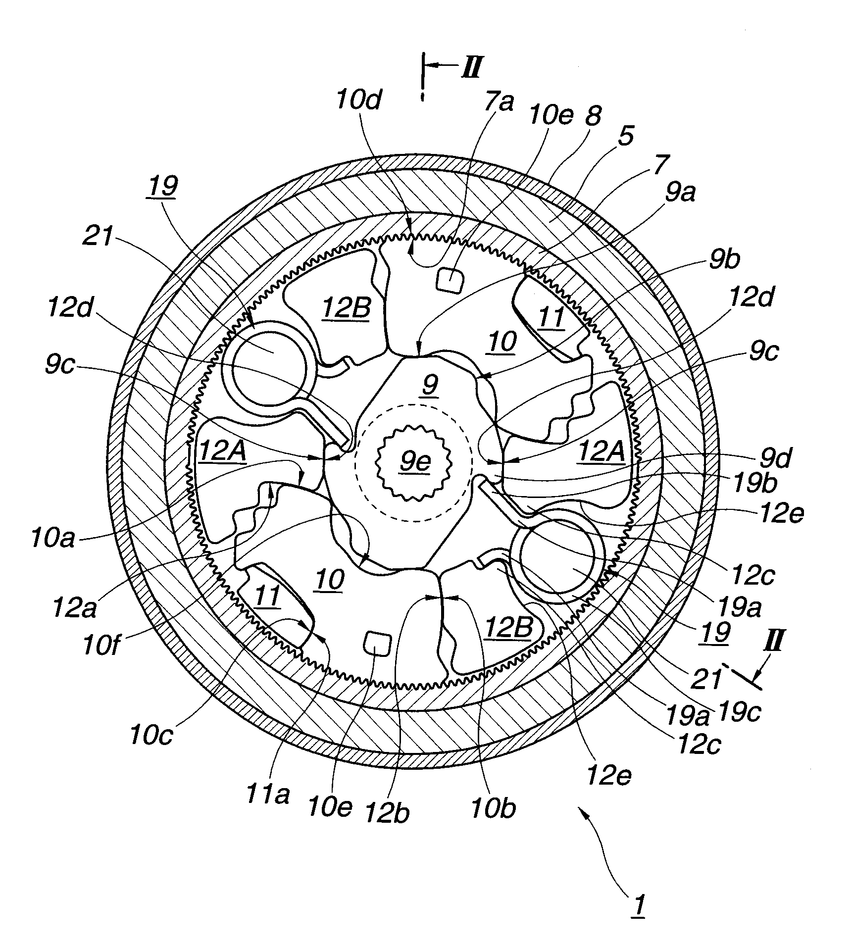
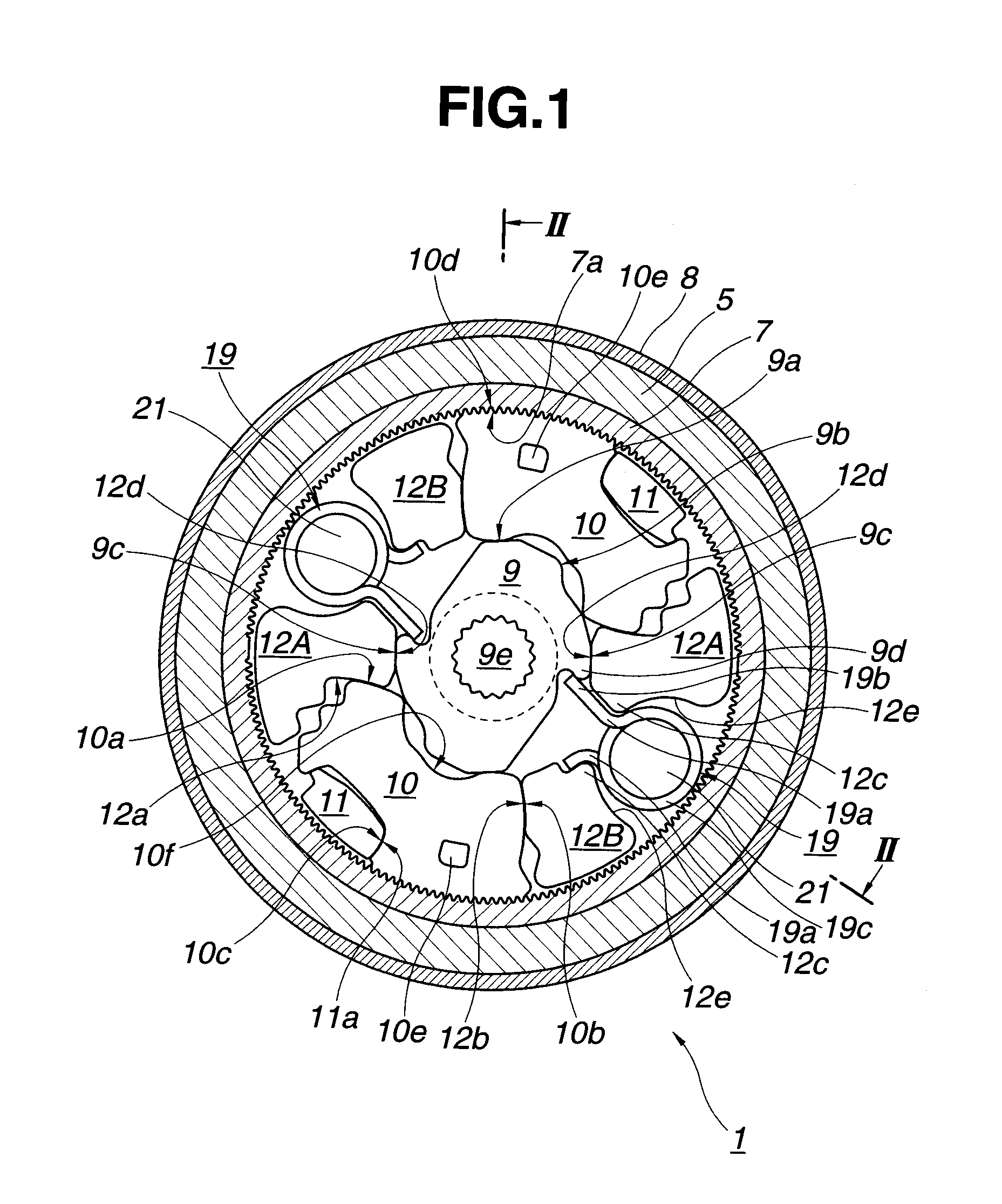
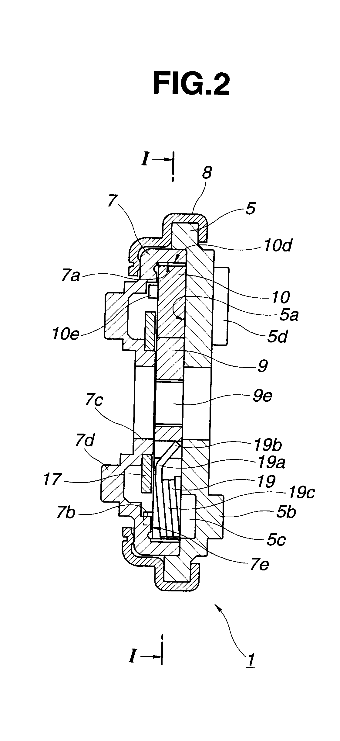
[0017]Referring now to the drawings, particularly to FIG. 7, the vehicle seat reclining device of the embodiment is exemplified in a car seat. This seat includes a seat cushion 2 serving as a seat part, and a seatback 3 installed on seat cushion 2 in such a manner as to pivot with respect to the seat cushion in a fore-and-aft direction of the car. A substantially disk-shaped machine frame (hereinafter is referred to as “stationary flange member”) 5 is connected via a base bracket 4 to the framework of the seat cushion side, whereas a substantially disk-shaped side cover (hereinafter is referred to as “movable flange member”) 7 is connected via an arm bracket 6 to the framework of the seatback side. A return spring (not shown) is provided to permanently force and incline or pivot the seatback 3 with respect to the seat cushion 2 forwardly of the vehicle (leftwards, viewing FIG. 7).

[0018]The previously-noted stationary flange member 5 and movable flange member 7 construct the vehicle ...


PUM

PropertyMeasurementUnit
bending angleaaaaaaaaaa
spring forceaaaaaaaaaa
forceaaaaaaaaaa

Abstract

A seat reclining device has a torsion spring for a cam, and a plurality of guide-protrusion pairs formed integral with the inside face of a stationary member for guiding movement of tooth blocks into and out of meshed-engagement with an internal tooth of a movable member. Two opposing circular-arc concave portions are formed on opposing faces of two circumferentially adjacent guide-protrusion sets. A space between the concave portions is dimensioned to be wider on a radially outward side for defining a spring accommodation space, and dimensioned to be narrower on a radially inward side for forming circumferentially-opposing convex portions. Two spring hooks engage with the respective convex portions under preload. One of the hooks is also engaged with the cam for forcing it in its locked direction. An anti-rotation protrusion is formed on the outside face of the stationary member at a position conforming to the spring accommodation space.

Description

TECHNICAL FIELD[0001]The present invention relates to a vehicle seat reclining device configured to enable angular position adjustment of a seatback relative to a seat cushion in an unlocked state of lock tooth blocks displaceable by a cam and also configured to hold the relative angular position of the seatback in a locked state of the lock tooth blocks, and specifically to the improvement of a supporting structure of a spring by which the cam is permanently biased so that the lock tooth blocks are forced toward their locked positions.BACKGROUND ART[0002]A car seat is generally equipped with a seat reclining device by which an angular position of a seatback with respect to a seat cushion can be varied. One such vehicle seat reclining device has been disclosed in Japanese Patent Provisional Publication No. 2008-212176 (hereinafter is referred to as “JP2008-212176”), corresponding to United States Patent Application Publication No. US 2008 / 0203799 A1, published Aug. 28, 2008 and assi...

Claims


Application Information

Patent Timeline
Patent Type & Authority Applications(United States)
IPC IPC(8): B60N2/235B23P11/02
CPCY10T29/49863B60N2/2356B60N2/2362
Inventor IGUCHI, DAISUKE
Owner TF METAL CO LTD
Why Eureka
Try Eureka