Spindle motor

a spindle motor and spindle body technology, applied in the direction of dynamo-electric machines, electrical apparatus, supports/enclosements/casings, etc., can solve the problems of degrading the reliability of the product, cumbersome and inconvenient work, and difficult stopper b, so as to improve the coupling structure

Inactive Publication Date: 2010-08-05
HITACHI LG DATA STORAGE KOREA
View PDF9 Cites 0 Cited by
  • Summary
  • Abstract
  • Description
  • Claims
  • Application Information

AI Technical Summary

Benefits of technology

[0008]An object of the present invention is to obviate the abovementioned problems, and it is an object to provide a spindle motor that has improved a coupled structure between a stopper and a rotor yoke.

Problems solved by technology

The conventional spindle motor thus configured is coupled to the rotor yoke 21a by way of welding, such that foreign objects generated from the welding are sticked to and stiffened at the stopper 25 or the rotor yoke 21a. The conventional spindly motor suffers from a disadvantage in that the foreign objects contact other parts to cause defects such as noise generation and the like, thereby degrading the reliability of the product.
The conventional spindle motor suffers from another disadvantage in that workability is cumbersome and inconvenient due to use of a welding machine for coupling the stopper 25 to the rotor yoke 21a. Furthermore, the conventional spindle motor suffers from still another disadvantage in that the welded coupling between the stopper 25 and the rotor yoke 21a makes it difficult for the stopper 25 to be separated from the rotor yoke 21a without damages to the stopper and the rotor yoke, whereby it is difficult to repair and re-use the stopper and the rotor yoke, and it is also uneconomical to dispose of the stopper and the rotor yoke due to high disposal cost.

Method used


Image

  • Spindle motor
  • Spindle motor
  • Spindle motor

Examples


Embodiment Construction

[0016]A spindle motor according to the exemplary embodiments of the present invention will be described in detail with reference to the accompanying drawings.

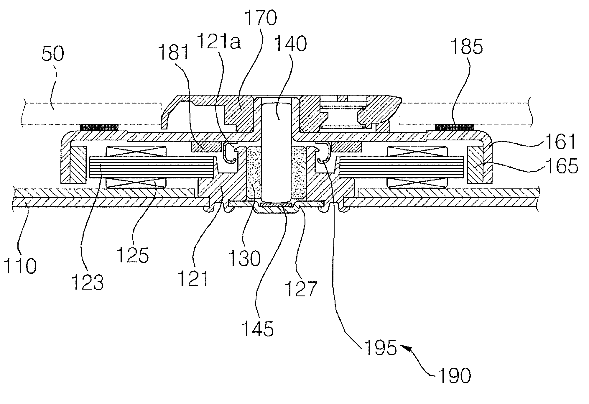
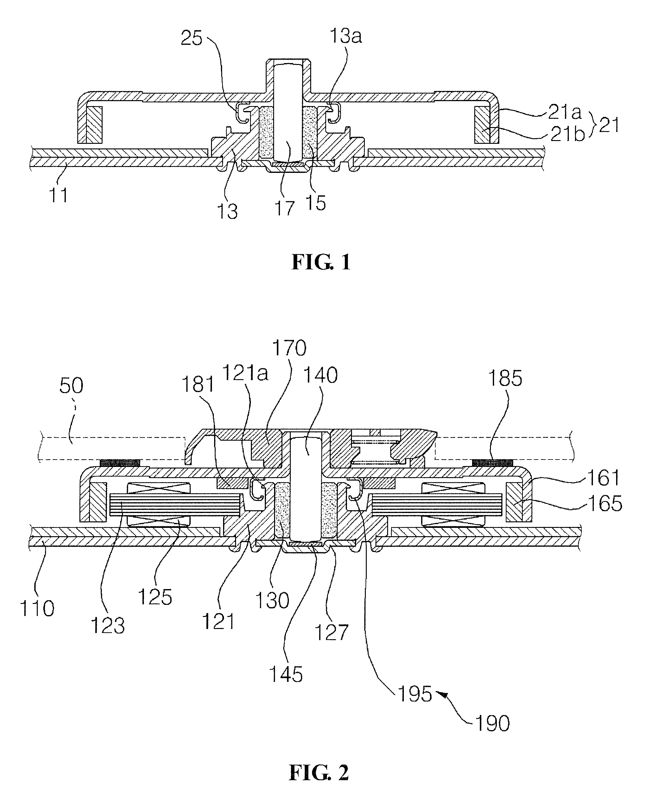
[0017]FIG. 2 is a cross-sectional view illustrating a spindle motor according to an exemplary embodiment of the present invention.

[0018]A base is provided as shown in FIG. 2. In designating a direction and a surface of constituent parts, a direction and a surface facing an upper vertical side of the base 110 are respectively called “an upper side” and “an upper surface”, while a direction and a surface facing a bottom vertical side of the base are respectively called “a bottom side” and “a bottom surface”. A stator is provided at an upper surface of the base 110.

[0019]The stator includes a cylindrical bearing housing 121 with upper and bottom surfaces being opened and the bottom surface being coupled to the base 110, a core 123 fixed at a periphery of the bearing housing 121, and a coil 125 wound on the core 123.

[0020]A thrust ...


PUM


Abstract

A spindle motor is disclosed, wherein a coupling protruder of a stopper is penetrated into a rotor yoke by caulking. Therefore, no foreign objects that are generated from welding process are produced to inhibit the spindle motor from generating defects caused by the foreign objects and to improve the product reliability. Furthermore, the coupled protruder of the stopper is coupled to the rotor yoke by caulking, to make an assembly process simple. Still furthermore, the spindle motor according to the present invention is economical in that, in a case the coupled stopper is to be separated from the rotor yoke, the coupled stopper and the rotor yoke can be simply separated by cutting off a caulked portion of the coupled protruder, thereby allowing the rotor yoke to be re-used.

Description

CROSS-REFERENCE TO RELATED APPLICATION[0001]This application claims the benefit under 35 U.S.C. §119 of Korean Application No. 10-2009-0008399, filed Feb. 3, 2009, which is hereby incorporated by reference in its entirety.BACKGROUND[0002]A spindle motor performs the function of rotating a disk to enable an optical pickup which linearly reciprocates in an optical disk drive (ODD) to read data recorded on the disk.[0003]FIG. 1 is a cross-sectional view illustrating essential parts of the conventional spindle motor.[0004]Referring to FIG. 1, a bearing 15 is fixed at an interior of a bearing housing 13 formed at a base 11, and the bearing 15 is rotatably supported by a rotation shaft 17. A rotor 21 having a rotor yoke 21a and a magnet 21b is coupled to a periphery of the rotation shaft 17 exposed toward an upper surface of the bearing housing 13. The rotor 21 cooperatively rotate with a stator (not shown) fixed at the periphery of the bearing housing 13.[0005]An outwardly extended hitch...

Claims


Application Information

Patent Timeline
Patent Type & Authority Applications(United States)
IPC IPC(8): H02K5/167
CPCH02K5/1675H02K5/165H02K5/24
Inventor YOON, HO EOP
Owner HITACHI LG DATA STORAGE KOREA
Why Eureka
Try Eureka