
Spindle motor

Inactive Publication Date: 2010-08-05
HITACHI LG DATA STORAGE KOREA
View PDF10 Cites 4 Cited by
  • Summary
  • Abstract
  • Description
  • Claims
  • Application Information

AI Technical Summary

Benefits of technology

[0007]An object of the present invention is to obviate the abovementioned problems, and it is an object to provide a spindle motor configured to improve a coupling structure between a base and a bearing housing, thereby promoting a reduced number of parts, a reduced assembly process and an improved perpendicularity and assemblage.

Problems solved by technology

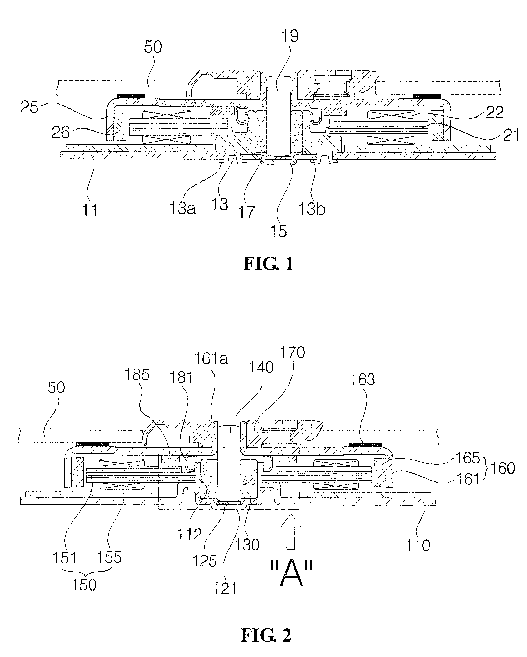
The spindle motor thus described suffers from a disadvantage in that a work process is complicated to increase the manufacturing cost because the base 11 and the bearing housing 13, and the bearing housing 13 and the thrust stopper 15 are mutually coupled by caulking 13a, 13b.
The conventional spindle motor also suffers from a disadvantage in that a bearing housing 13 made of high priced brass is separately needed to further increase the manufacturing cost.
The conventional spindle motor still suffers from a disadvantage in that the rotation shaft 19 installed inside the bearing housing 13 may tilt relative to the base 11 because perpendicularity of the bearing housing 13 relative to the base 11 is deviated during caulking 13a process of the bearing housing 13, resulting in generation of noise and vibration.

Method used


Image

  • Spindle motor
  • Spindle motor
  • Spindle motor

Examples


Embodiment Construction

[0013]A spindle motor according to an exemplary embodiment of the present invention will be described in detail with reference to the accompanying drawings.

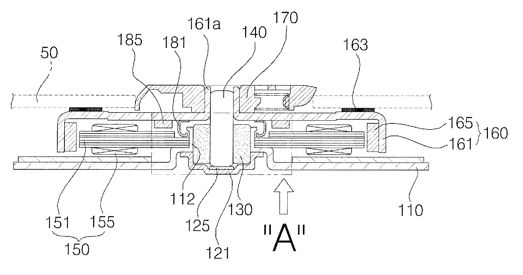
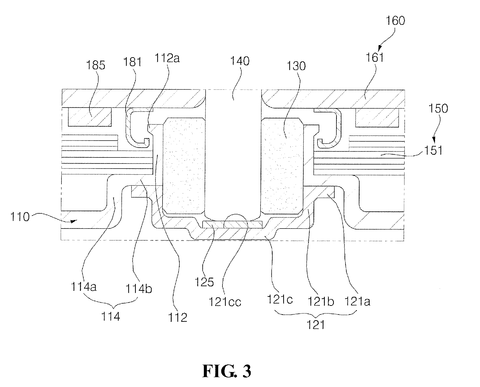
[0014]FIG. 2 is a cross-sectional view illustrating a spindle motor according to an exemplary embodiment of the present invention, and FIG. 3 is an enlarged view of “A” part of FIG. 2.

[0015]As illustrated, a spindle motor according to the present invention is installed with a base 110. In designating a direction and a surface of constituent parts including the base 110, a direction and a surface facing an upper vertical side of the base 110 are respectively called “an upper side” and “an upper surface”, while a direction and a surface facing a bottom vertical side of the base are respectively called “a bottom side” and “a bottom surface”. A stator is provided at an upper surface of the base 110.

[0016]The base 110 is coupled with a thrust stopper 121 airtightly sealing a bottom surface of a support portion 112 by welding or adhesi...


PUM


Abstract

A spindle motor is disclosed, whereby a bearing is fixed at a support portion of a base to dispense with a bearing housing, thereby reducing the number of parts, shortening an assembly process and reducing the manufacturing cost. Furthermore, the bearing is fixedly inserted into the support portion integrally formed with the base to allow the bearing to maintain a perpendicularity relative to the base, whereby a rotation shaft supported by the bearing can maintain a perpendicularity, thereby reducing noise and vibration.

Description

CROSS-REFERENCE TO RELATED APPLICATION[0001]This application claims the benefit under 35 U.S.C. §119 of Korean Application No. 10-2009-0008408, filed Feb. 3, 2009, which is hereby incorporated by reference in its entirety.BACKGROUND[0002]A spindle motor performs the function of rotating a disk to enable an optical pickup which linearly reciprocates in an optical disk drive (ODD) to read data recorded on the disk.[0003]FIG. 1 is a cross-sectional view of the conventional spindle motor. Referring to FIG. 1, an assembly process of a spindle motor is such that a base 11 is supportively coupled with upper / bottom-opened bearing housing 13. An outer bottom end of the bearing housing 13 is coupled to the base 11 by caulking, and an inner bottom end of the bearing housing 13 is coupled to a thrust stopper 15 by caulking.[0004]A bearing 17 is coupled to an interior of the bearing housing 13, and the bearing 17 is rotatably supported by a rotation shaft 19. An outer surface of the bearing hous...

Claims


Application Information

Patent Timeline
IPC IPC(8): H02K5/167
CPCF16C35/02G11B19/2009F16C2370/12H02K7/09H02K5/1675H02K5/15H02K5/16
Inventor JUNG, HEE CHUL
Owner HITACHI LG DATA STORAGE KOREA
Learn More