Filter for electronic signals and method for manufacturing it

An electronic signal and filter technology, applied in waveguide-type devices, circuits, electrical components, etc., can solve problems such as insufficient meaning of control matching and coupling, lack of optimization, and inability to fully control the direction and distribution of the excitation electric field.

Inactive Publication Date: 2010-01-20
NOKIA SOLUTIONS & NETWORKS OY
View PDF0 Cites 11 Cited by
  • Summary
  • Abstract
  • Description
  • Claims
  • Application Information

AI Technical Summary

Problems solved by technology

[0015] The disadvantage of the known couplings is that they are not optimized in the sense of matching or coupling efficiency or mode / frequency selection
Current Mode Coupling ( figure 1 e) good tuning of the excitation current for the resonant current of the desired primary resonant mode, but perhaps not sufficiently in the sense of controlling matching and coupling
Voltage-mode coupling roughly establishes a suitable electric field for coupling a sufficient amount of energy into the filter in the fundamental mode, but it also tends to excite other modes because the direction and distribution of the excited electric field cannot be adequately controlled

Method used


Image

  • Filter for electronic signals and method for manufacturing it
  • Filter for electronic signals and method for manufacturing it
  • Filter for electronic signals and method for manufacturing it

Examples


Embodiment Construction

[0031] In general, the features described in this specification are to be regarded as being combinable with each other to the extent technically possible, even if this is not explicitly stated. Like reference numerals will refer to like parts.

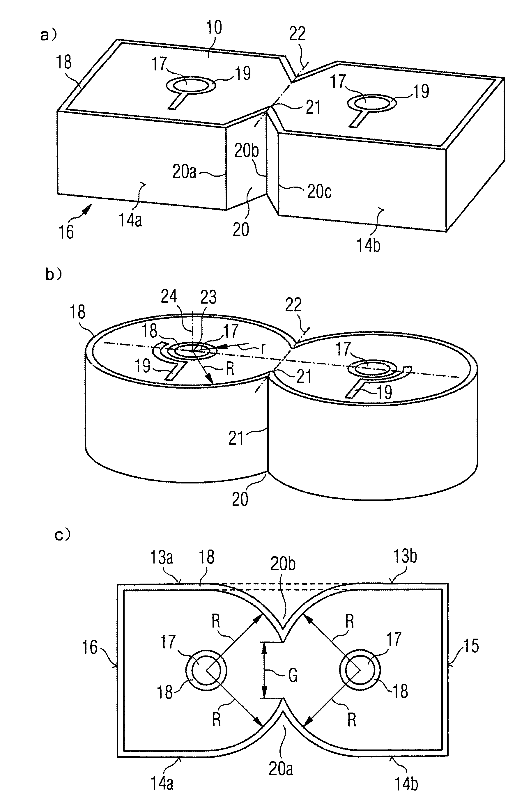
[0032] figure 2 A first embodiment of the invention is shown, showing a modified shape of the filter. The filter may be a ceramic monolithic filter as already stated. Unless otherwise stated below, the filter according to the present invention may have the same figure 1 Characteristics described in a-1e.

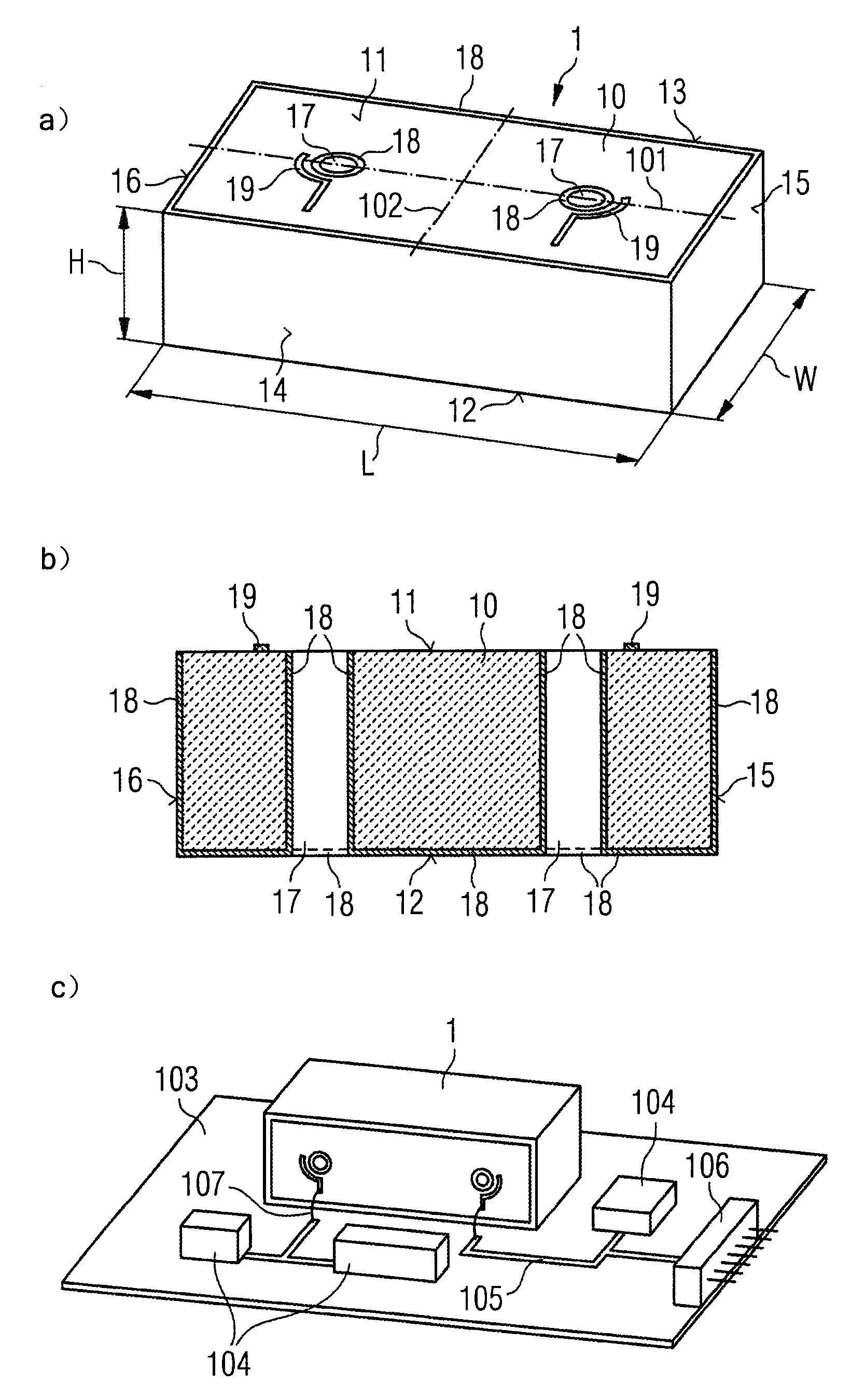
[0033] The body 10 of the filter 1 has a first surface 11 from which there are two holes 17, which may be resonator holes, which extend into the body, preferably perpendicular to the first surface 11, and preferably through the entire Body to second surface 12 (not visible). a surface of the body 10, namely figure 2 A fourth surface 14 in the body, from which the hole does not extend, has a recess 20 protruding into the body,...


PUM

PropertyMeasurementUnit
lengthaaaaaaaaaa
widthaaaaaaaaaa

Abstract

A filter (1) for electronic signals comprises a dielectric body (10), at least two coupling structures (19, 40 - 42) for coupling in and coupling out electronic signals, and one or more conductors (18) on surface portions of the body, wherein an outer surface of the body comprises one or more indentations (20). The coupling structure (40) comprises a coupling conductor (42) for signal input and / or output, and in relation to an end portion (42b) of said conductor a coupling hole (41) extending from said first surface and / or from a second surface opposite the first surface into the body.

Description

technical field [0001] The invention relates to a filter for electronic signals and a method for its manufacture. The filter under consideration may be a filter having a ceramic body with appropriate metallization on it, such as a ceramic monolithic filter. Background technique [0002] For reasons of size and cost, ceramic single-mode monolithic filters are used in small and medium power Base Transmit Site (BTS) products. Electronic performance is also satisfied, especially with the increased size of the filter body. This causes the rectangular filter body to start passing electromagnetic energy in the higher resonant modes, and to start leaking energy beyond a certain cutoff frequency. The smaller the subject, the higher the cutoff frequency. It is roughly related to the formula: 1 / ((εr)1 / 2×W×L). Such leakage is caused by undesired higher propagation modes in the ceramic material. It is analogous to propagation in a waveguide that is larger than one required to allow ...

Claims


Application Information

Patent Timeline
Patent Type & Authority Applications(China)
IPC IPC(8): H01P1/20H01P1/212H01P11/00
CPCH01P1/2056Y10T29/49002
Inventor M·E·埃姆特卢J·T·帕洛南
Owner NOKIA SOLUTIONS & NETWORKS OY
Why Eureka
Try Eureka