Robust on line stator turn fault identification system

a stator and turn fault technology, applied in the direction of motor/generator/converter stopper, dynamo-electric converter control, instruments, etc., can solve the problems of manufacturing defects, failures of the number or types of components, motor components or the motor itself,

Active Publication Date: 2010-08-05
GENERAL ELECTRIC CO
View PDF15 Cites 12 Cited by
  • Summary
  • Abstract
  • Description
  • Claims
  • Application Information

AI Technical Summary

Problems solved by technology

In many environments, the windings in the stator are subject to shorts between the turns of the windings, commonly referred to as “turn faults.” Depending on the material used for the windings and the insulation, any number or types of failures may occur.
Such failures may be mechanical, chemical, or electrical, and may result from degradation of the insulation, the winding material, a manufacturing defect, etc.
These turn faults gradually result in extended failures of the windings and eventually result in failure, leading to replacement or repair of motor components or the motor itself.
The repair or replacement of the motor or motor components may be unforeseeable and create undesirable downtime in the application or process using the motor when the motor is taken offline.

Method used


Image

  • Robust on line stator turn fault identification system
  • Robust on line stator turn fault identification system
  • Robust on line stator turn fault identification system

Examples


Embodiment Construction

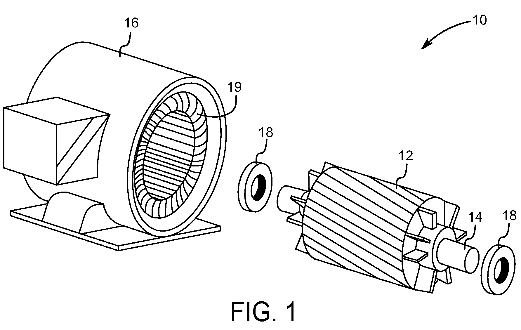
[0015]FIG. 1 is a diagrammatical perspective illustration of an induction motor 10. FIG. 1 is provided for illustrative purposes only, and embodiment of the present invention are not limited to any specific induction motor or configuration thereof. In the illustrated example, the motor 10 includes a rotor assembly 12, which includes a rotor shaft 14 extending through a rotor core. The rotor assembly 12 along with the shaft 14 can rotate inside the stator assembly 16. Bearing assemblies 18 that surround the rotor shaft 14 may facilitate such rotation within the stator assembly 16. The stator assembly 16 includes a plurality of stator windings 19 that extend circumferentially around and axially along the rotor shaft 14 through the stator assembly 16. During operation, a rotating magnetic field induced in the stator windings 19 reacts with the induced current in the rotor assembly 12 to cause the rotor assembly 12 to rotate, converting electrical energy to mechanical energy output thro...


PUM


Abstract

A system and method for identifying turn faults in a stator of a motor are provided. The method includes determining a normalized cross-coupled impedance from the symmetrical components of measured voltages and currents of the motor. Additionally, the normalized cross-coupled impedance may be normalized to a negative sequence impedance. The negative sequence impedance may be determined through a regression analysis using parameters of the motor, such as line-to-line voltage, horsepower, and number of poles. A system is provided that includes a device having a memory and processor configured to determine a normalized cross-coupled impedance, compare the normalized cross-coupled impedance to one or more thresholds, and trigger and alarm and/or trip the motor.

Description

BACKGROUND[0001]The invention relates generally to detecting turn faults in the stator of alternating current (AC) induction motors.[0002]AC induction motors are used in a wide array of applications and processes. An AC induction motor typically includes a stationary portion, a “stator,” and a rotating portion, a “rotor.” In a 3-phase AC motor, power is applied to the stator to induce a magnetic field, causing the rotor to turn and generate mechanical energy. The stator may include any number of “windings,” or wound poles that carry the current necessary to induce the magnetic field. These windings may also be characterized by the “turns” in the windings.[0003]In many environments, the windings in the stator are subject to shorts between the turns of the windings, commonly referred to as “turn faults.” Depending on the material used for the windings and the insulation, any number or types of failures may occur. Such failures may be mechanical, chemical, or electrical, and may result...

Claims


Application Information

Patent Timeline
Patent Type & Authority Applications(United States)
IPC IPC(8): H02H7/08
CPCG01R31/343
Inventor PREMERLANI, WILLIAM JAMESR., SOMAKUMARTIWARI, ARVIND KUMARSEN, BHASKARKASZTENNY, BOGDAN Z.BANERJEE, ARIJIT
Owner GENERAL ELECTRIC CO
Why Eureka
Try Eureka