Method and apparatus for monitoring operational performance of fluid storage systems

a technology of fluid storage system and monitoring method, which is applied in the direction of liquid transfer device, mechanical measuring arrangement, instruments, etc., can solve the problems of not being temperature compensated, difficult or impossible to direct observation of the operation condition of such storage containers and storage containers, and the accuracy of the device which measures the amount of product dispensed from storage containers and tanks differs

Inactive Publication Date: 2005-08-23
WARREN ROGERS ASSOC
View PDF47 Cites 49 Cited by
  • Summary
  • Abstract
  • Description
  • Claims
  • Application Information

AI Technical Summary

Benefits of technology

[0027]FIG. 13 is a schematic diagram of an underground st

Problems solved by technology

Direct observation of the operating condition of such tanks and storage containers is difficult or impossible.
Moreover, the accuracy of devices which measure the amount of product dispensed from the storage containers and tanks differs greatly, and may or may not be temperature compensated.
The amount of product actually delivered to the tank system is often measured inaccurately and, frequently, not at all.
Consequently, effective management of such facilities is complicated by the numerous errors in the various measuring devices and procedures used to establish a baseline for management, planning and d

Method used


Image

  • Method and apparatus for monitoring operational performance of fluid storage systems
  • Method and apparatus for monitoring operational performance of fluid storage systems
  • Method and apparatus for monitoring operational performance of fluid storage systems

Examples


Embodiment Construction

[0028]The method and apparatus described herein applies to UST's, AST's or any type of storage tank. The product stored in the tank may be any fluid, including dry particles that flow in the manner of a fluid.

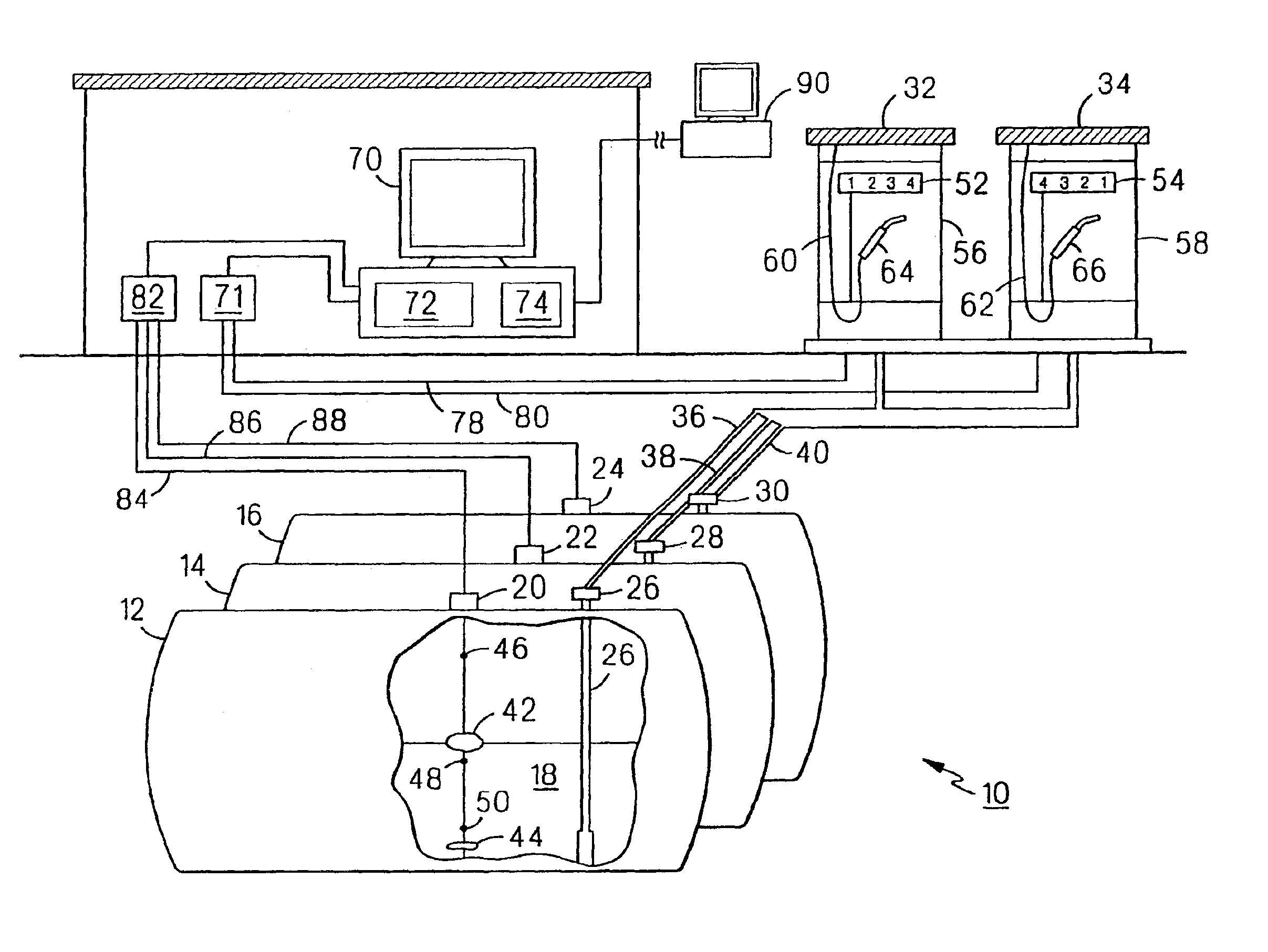
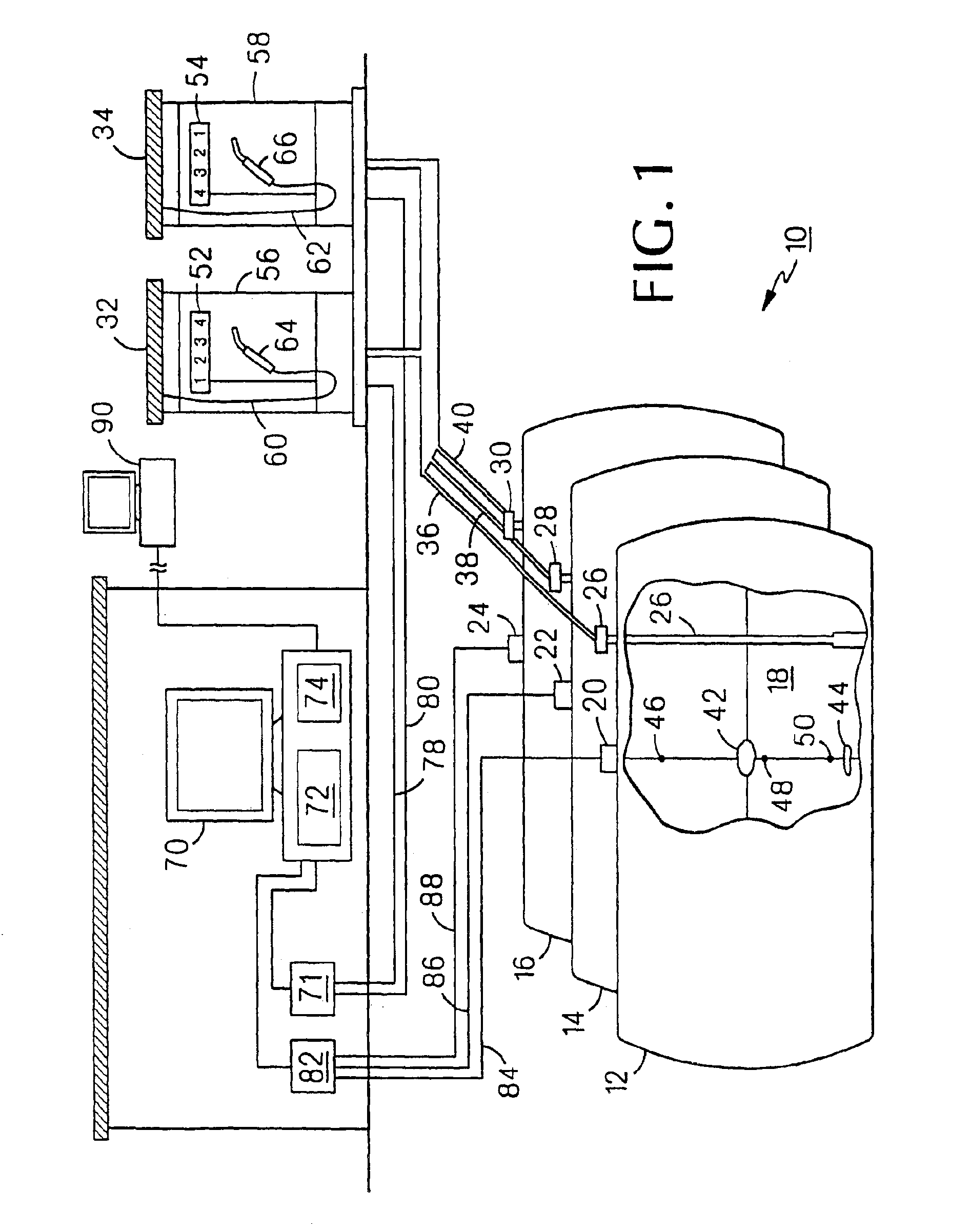
[0029]FIG. 1 shows a UST facility 10, illustrated as an automobile service station. Facility 10 includes a series of UST's 12, 14, 16 which may store the same or different types of liquid fuel product 18. Volumetric tank gauges 20, 22, 24 in each tank measure the height of product 18 in the tank. Submersible pumps 26, 28, 30 in each tank pump product 18 to one of dispensing pumps 32, 34 through piping lines 36, 38, 40. Alternately, facility 10 may be an AST facility with above-ground tank 1000, as shown in FIG. 11, or a facility with a partially above-ground tank 1010, as shown in FIG. 12.

[0030]Tank gauges 20, 22, 24 are mounted in tanks 12, 14, 16. The tank gauges may consist of or be based on magnetostrictive tank probes or other sensing technologies. In the cases of magnetos...


PUM


Abstract

A method of determining a volume of fluid associated with a fluid storage and dispensing system, the volume of fluid having a height in the system, wherein the system include measurement apparatus for measuring the height. The method includes collecting a plurality of height measurement data from the measurement apparatus in a form readable by a computer; storing the plurality of height measurement data in a compressed matrix format in a computer memory; and performing regression analysis using the compressed matrix format to calculate the volume of fluid associated with the system.

Description

CROSS-REFERENCE TO RBLATED APPLICATIONS[0001]This application is a continuation-in-part of U.S. application Ser. No. 09 / 350,973, filed Jul. 9, 1999, now U.S. Pat. No. 6,691,061, which is a continuation-in-part of U.S. application Ser. No. 09 / 083,732, filed May 22, 1998, which issued on Jun. 4, 2002 as U.S. Pat. No. 6,401,045 B1, which in turn is a continuation-in-part of both U.S. application Ser. No. 08 / 658,139, filed Jun. 4, 1996, which issued on May 26, 1998 as U.S. Pat. No. 5,757,664 B1, and International Application No. PCT / US97 / 09505, which designated the United States and was filed on Jun. 4, 1997 and was published in English. The entire teachings of the above applications are incorporated herein by reference.BACKGROUNDDescription of the Background[0002]The invention relates to monitoring the operational performance of fluid storage systems.[0003]Large quantities of liquids and similar materials are often stored in bulk storage containers or tanks, which may be located above-...

Claims


Application Information

Patent Timeline
IPC IPC(8): B67D5/33B67D5/08B67D5/32G01F25/00G01F23/00B67D7/08B67D7/34
CPCB67D7/08B67D7/348G01F23/0069G01F23/0076G01F25/0007G01F23/802G01F23/804G01F25/10
Inventor ROGERS, WARREN F.COLLINS, JOHN R.JONES, JILLANNE B.
Owner WARREN ROGERS ASSOC
Why Eureka
Try Eureka