
Method of controlling an IGBT and a gate driver

a gate driver and gate technology, applied in the direction of oscillator details, pulse technique, electric pulse generator details, etc., can solve the problems of short time between voltage over the component and current through the component, tolerable turn-on and turn-off losses, and fast operation of igbt switches

Active Publication Date: 2010-08-05
ABB (SCHWEIZ) AG
View PDF18 Cites 11 Cited by
  • Summary
  • Abstract
  • Description
  • Claims
  • Application Information

AI Technical Summary

Benefits of technology

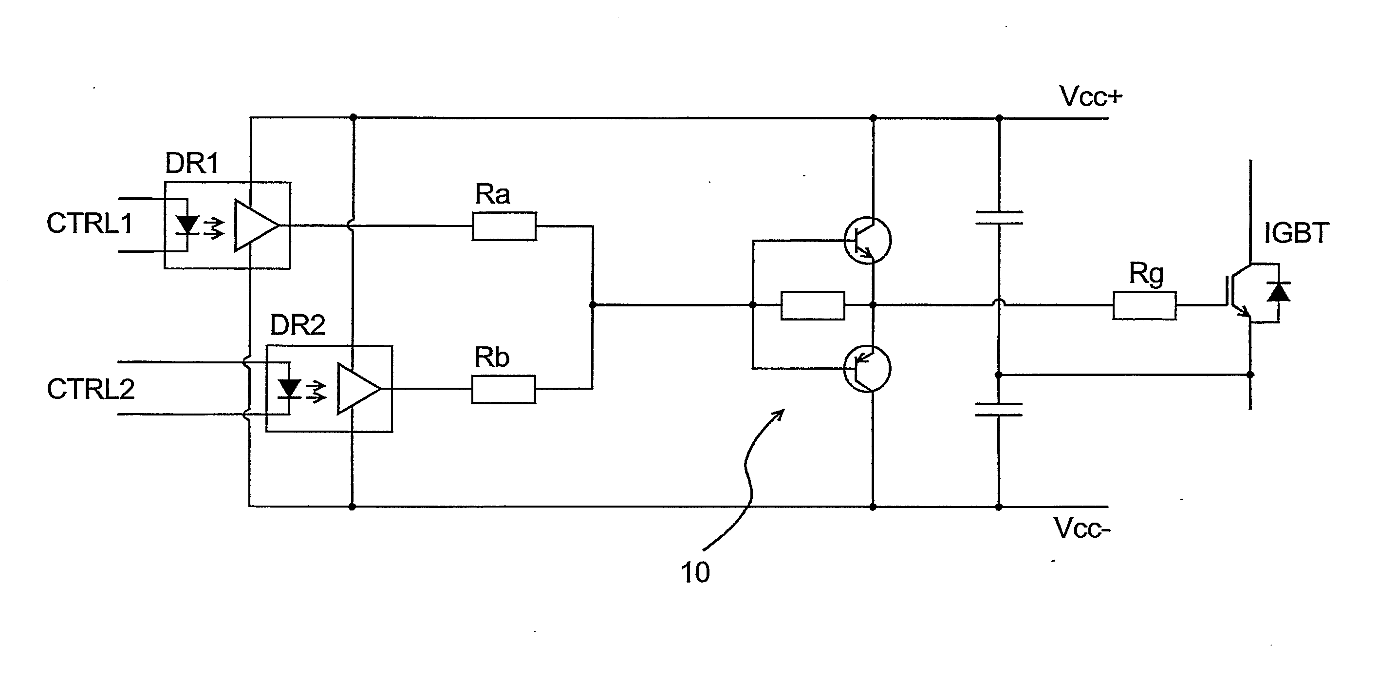
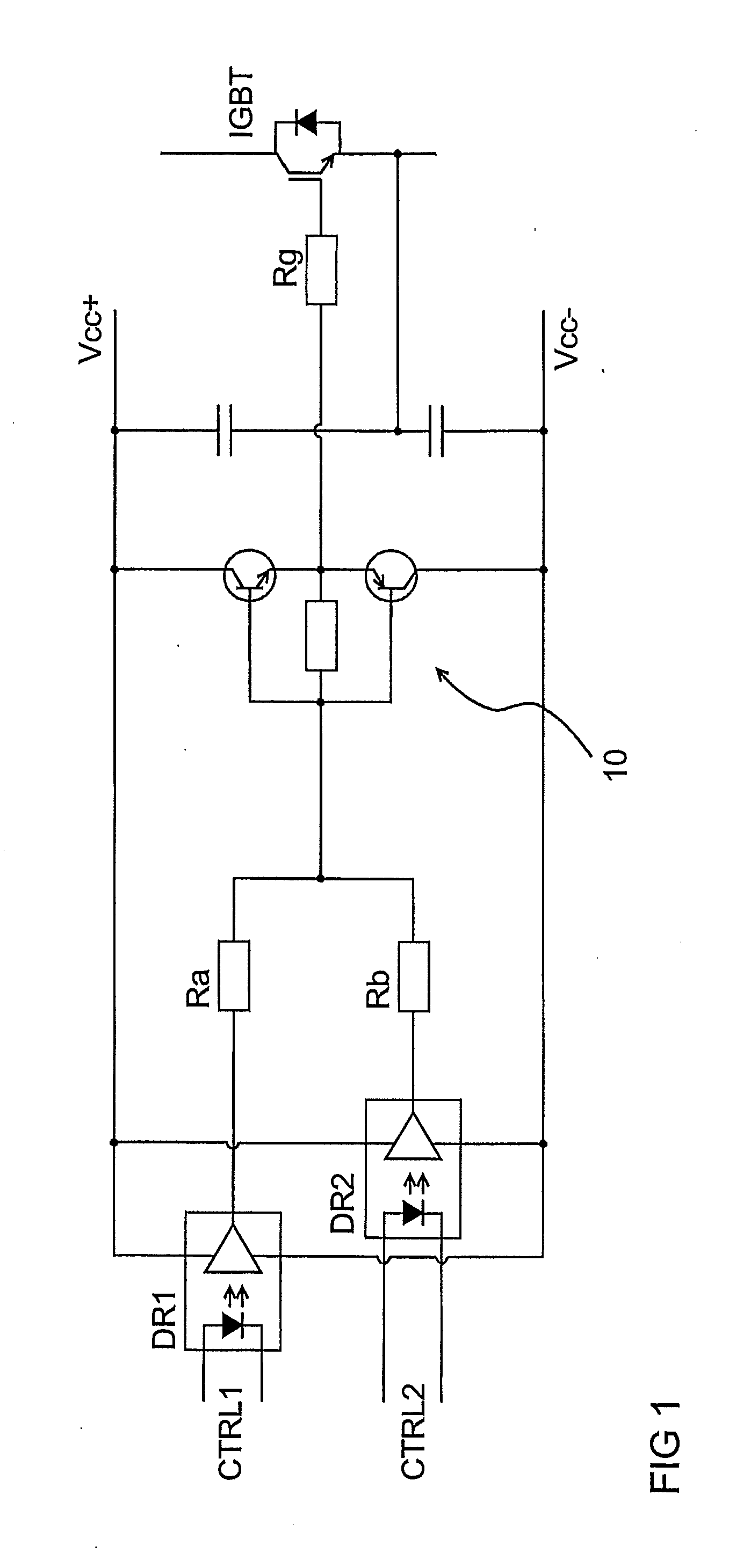
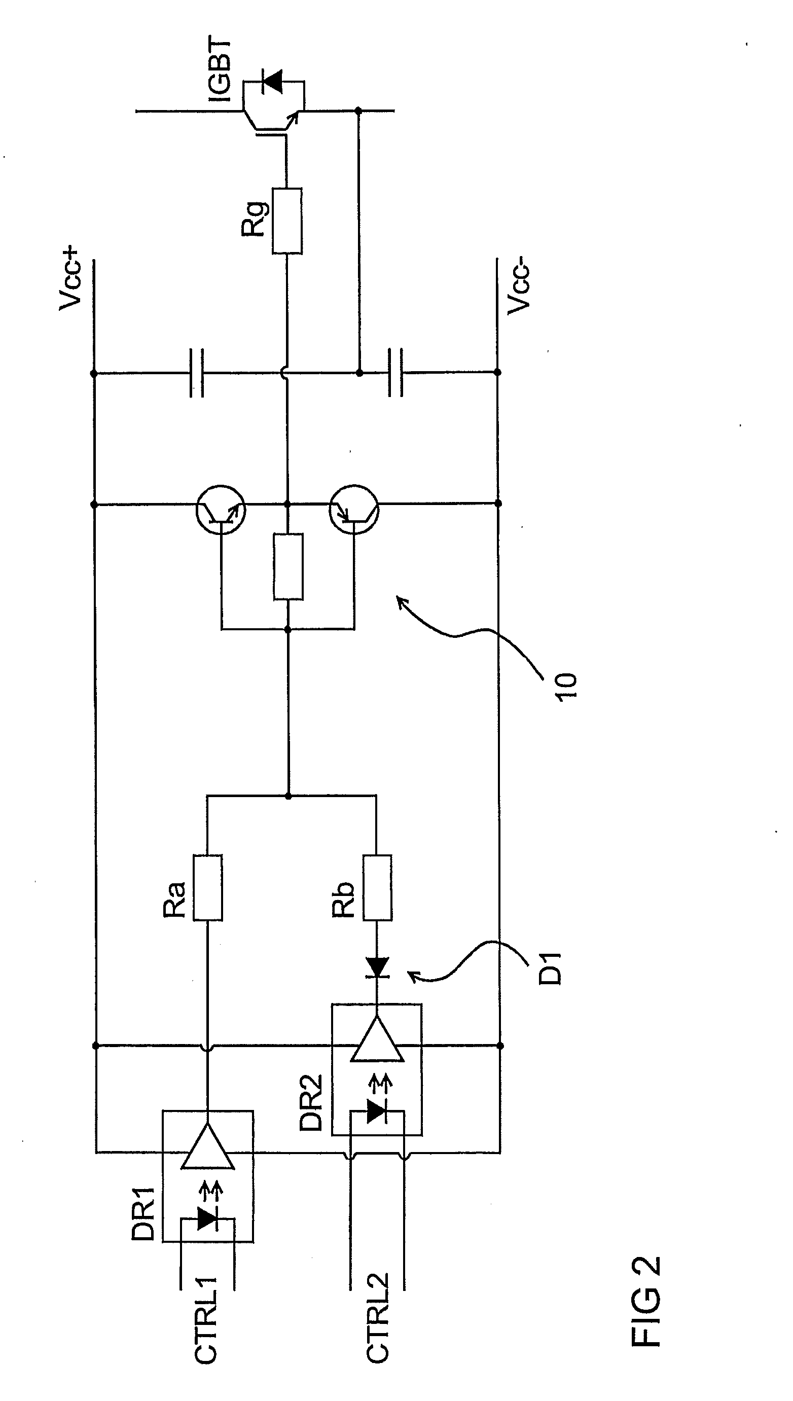
[0014]An exemplary embodiment can provide a soft shutdown feature with a minimum amount of extra components and this feature can be seamlessly integrated with normal turn-on and turn-off features in a gate driver. Exemplary embodiments, can be implemented with a simple design by using well-tested, known components. When the number of components is small, the space for the components is also small, thereby taking considerably less room in a housing of electrical equipment having the controlled IGBT switches.

Problems solved by technology

Further, IGBT switches are fast in operation, with tolerable turn-on and turn-off losses.
This is due to the fact that simultaneous time of the voltage over the component and current through the component is short.
The IGBT which is conducting an over current cannot be turned off in a normal manner, since the quick removal of excessive current would cause voltage spikes across the collector and emitter of the component.
This voltage spike could destroy the component and the devices connected to the component.
Known gate driver circuits which are also operable to remove short circuit current using soft shutdown can be complicated structures having many different components and therefore involving a large surface area.

Method used


Image

  • Method of controlling an IGBT and a gate driver
  • Method of controlling an IGBT and a gate driver
  • Method of controlling an IGBT and a gate driver

Examples


Embodiment Construction

[0013]A method and gate driven circuit are disclosed which include two control inputs for controlling an IGBT component. Resistive components can be connected to the output of these control inputs and, depending on the state of the control inputs, the resistive components form a voltage divider and set the gate of the controlled IGBT to a potential between the auxiliary voltages. This potential can be generated from the auxiliary voltage with the resistive voltage divider and is suitable for getting the IGBT softly from the over current state.

[0014]An exemplary embodiment can provide a soft shutdown feature with a minimum amount of extra components and this feature can be seamlessly integrated with normal turn-on and turn-off features in a gate driver. Exemplary embodiments, can be implemented with a simple design by using well-tested, known components. When the number of components is small, the space for the components is also small, thereby taking considerably less room in a hous...


PUM


Abstract

A method is disclosed for controlling an IGBT component and a gate driver. An exemplary method includes producing, with two separate driver circuits, a gate voltage for controlling the IGBT component, the outputs of the driver circuits being connected to free ends of a series connection of resistive components. A location, such as a midpoint between the series connection, forms the gate voltage.

Description

RELATED APPLICATION[0001]This application claims priority under 35 U.S.C. §119 to European Patent Application No. 09152138.5 filed in Europe on Feb. 5, 2009, the entire content of which is hereby incorporated by reference in its entirety.FIELD[0002]The present disclosure relates to gate drivers, such as gate drivers for insulated-gate bipolar transistors (IGBT).BACKGROUND INFORMATION[0003]IGBTs are power semiconductor components which are used, for example, as switches in high power applications. An IGBT is a gate controlled component, which can be turned on and off from its gate.[0004]The properties of IGBTs can make them very attractive to be used in high-power applications, since IGBT switches are able to switch high currents at high voltage levels. Further, IGBT switches are fast in operation, with tolerable turn-on and turn-off losses. This is due to the fact that simultaneous time of the voltage over the component and current through the component is short.[0005]IGBTs can incl...

Claims


Application Information

Patent Timeline
IPC IPC(8): H03B1/00H03K3/01
CPCH03K17/0828H03K17/168H03K17/166
Inventor NUUTINEN, LEO
Owner ABB (SCHWEIZ) AG
Learn More