Method and device for determining a distance from an object

a technology of distance and distance, applied in the direction of distance measurement, instruments, surveying and navigation, etc., can solve the problems of reducing the signal/noise ratio, reducing the accuracy of measurement, etc., to achieve the effect of large signal/noise ratio, high measurement accuracy, and large unambiguous rang

Active Publication Date: 2010-08-05
FARO TECH INC
View PDF3 Cites 52 Cited by
  • Summary
  • Abstract
  • Description
  • Claims
  • Application Information

AI Technical Summary

Benefits of technology

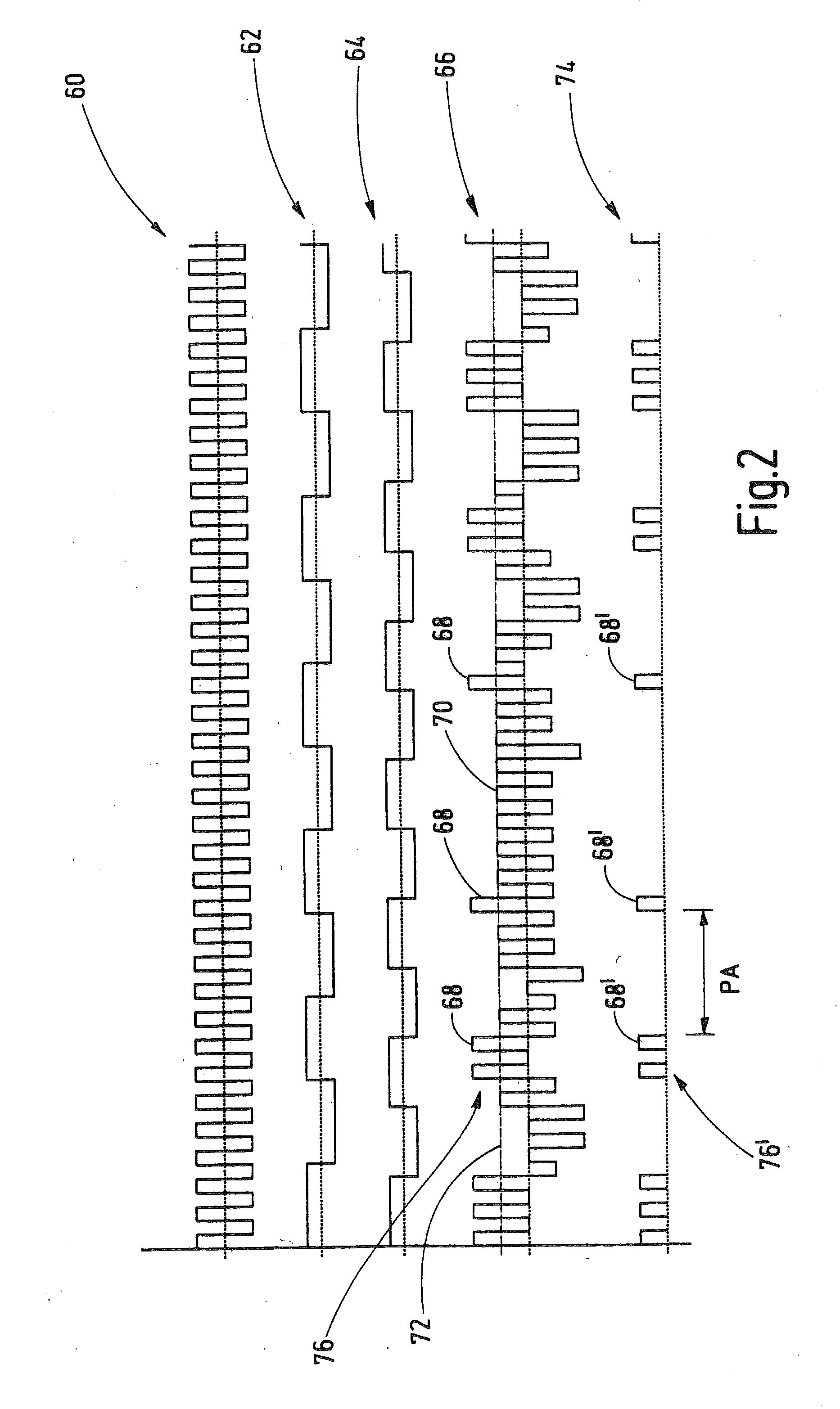
[0010]The novel method and the novel device are furthermore based on the principle of propagation time measurement according to the CW method, that is to say that the propagation time is determined on the basis of a phase shift of the modulation signal in the reception light beam relative to the modulation signal in the emission light beam. Furthermore, the novel method and the novel device use a rectangular-waveform modulation signal with which the emission light beam is amplitude-modulated. Though DE 40 27 990 C1 cited in the introduction has already considered a rectangular-waveform modulation signal for the amplitude modulation of a emission light beam, sinusoidal modulation signals are usually used in practice, by contrast. A rectangular-waveform modulation signal has the advantage over a sinusoidal modulation signal that the modulation signal remains at its respective maximum value for longer given the same signal amplitude (pulse peak) and the same modulation frequency. In other words, less light power is “wasted” for the edge rise in the case of a rectangular-waveform modulation signal. Consequently, the use of a rectangular-waveform modulation signal enables a higher signal / noise ratio than the use of a comparable sinusoidal modulation signal. The available light power can be utilized significantly better with a rectangular-waveform modulation signal.
[0036]In this configuration—which is also intrinsically inventive—the phase angle of the modulation signal in the emission light beam is determined metrologically and this phase is used as a reference for determining the propagation time. In other words, here the phase angle instantaneously present in the emission light beam is used for determining the propagation time. It is particularly preferred in this case if the light emitter comprises a laser diode and if the phase angle of the control current that flows through the laser diode is measured. The phase angle of the control current can be determined in a simple manner and it represents the actual instantaneous phase angle of the modulation signal in the emission light beam with high accuracy. This configuration enables a very high measuring accuracy because a phase drift in the region of the light emitter is eliminated from the distance determination.

Problems solved by technology

This is said to lead to a reduction of the signal / noise ratio and, consequently, to have the effect that objects having a low reflectivity can no longer be measured.
However, this method results in lengthened measuring times since each object has to be measured twice.
The higher measuring time is disadvantageous particularly in the case of a laser scanner, because the emission light beam can then only be pivoted relatively slowly.

Method used


Image

  • Method and device for determining a distance from an object
  • Method and device for determining a distance from an object
  • Method and device for determining a distance from an object

Examples


Embodiment Construction

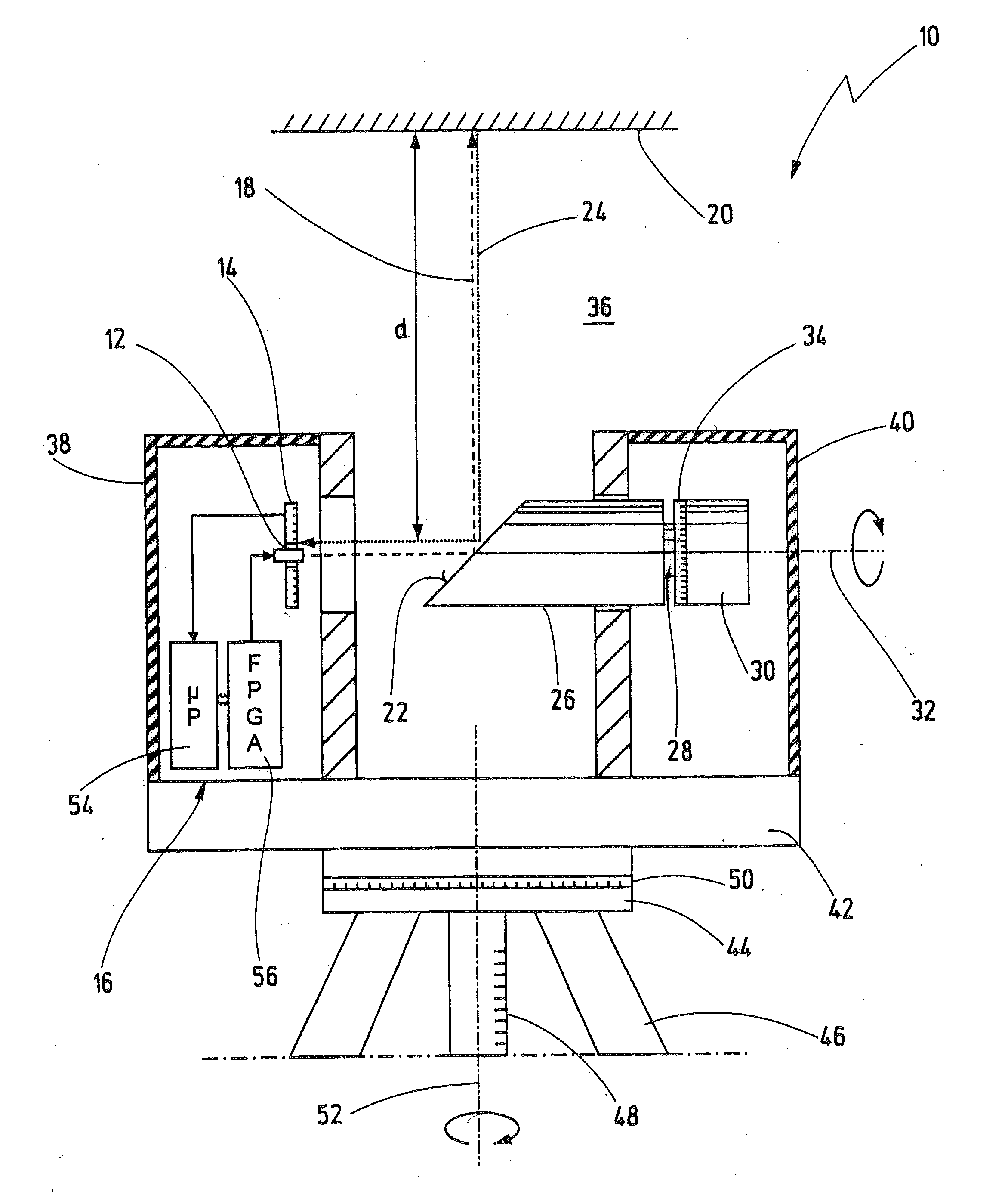
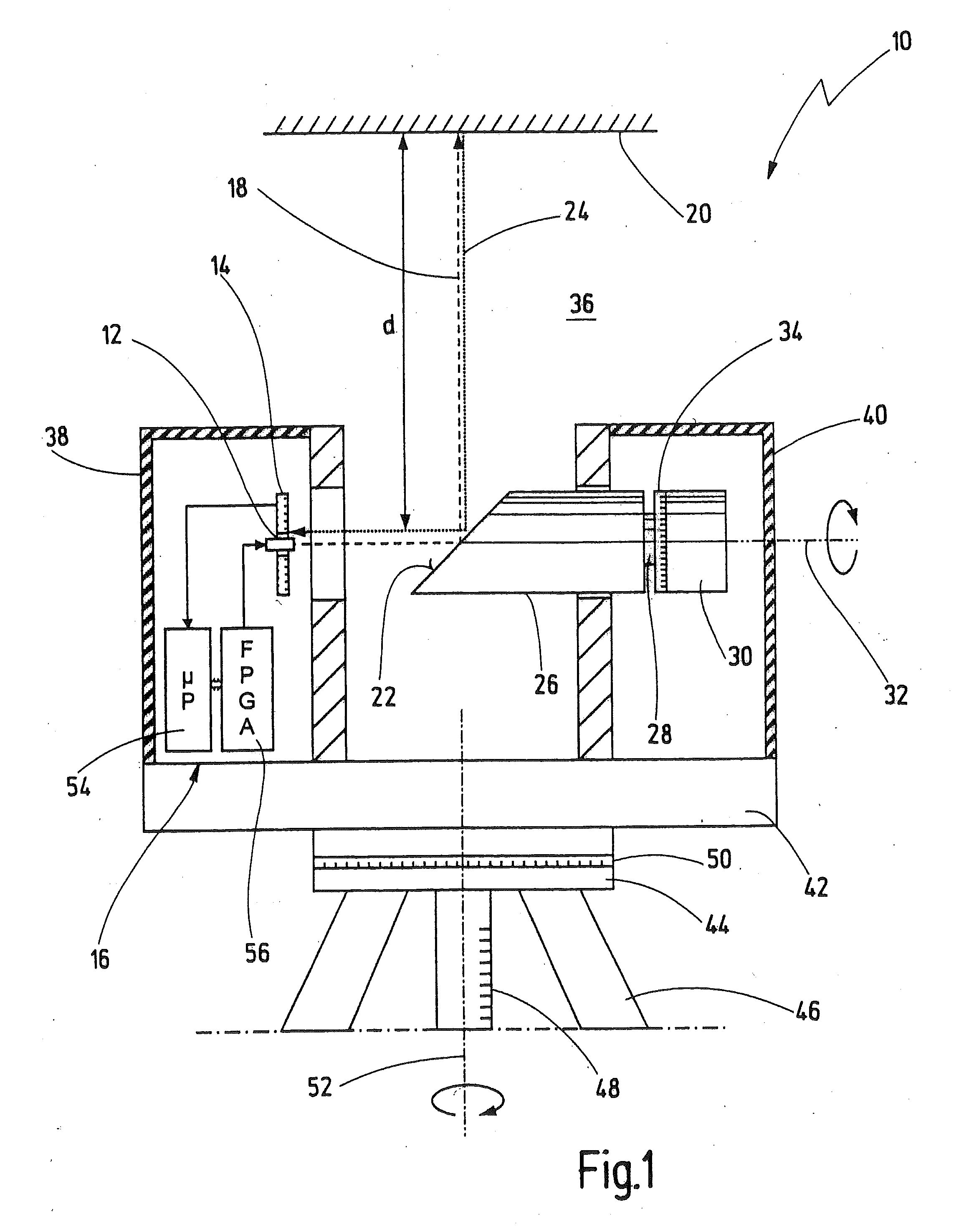
[0045]In FIG. 1, a laser scanner is designated in its entirety by the reference numeral 10. The laser scanner 10 is a an embodiment of a device according to the present invention. However, the novel device and the novel method can also be employed in other apparatuses in which a distance from an object is to be determined with the aid of a emission light beam and a reception light beam. The invention is also not restricted to the use of light beams in the narrower sense (preferred wavelengths between 300 and 1000 nm), but rather can in principle also be realized with electromagnetic waves from a larger wavelength range as long as a quasi-optical propagation is present. The expression light beam as used here therefore encompasses such electromagnetic waves as well.

[0046]The laser scanner 10 comprises a light emitter 12 and a light receiver 14, both of which are connected to an evaluation and control unit 16. In the preferred exemplary embodiment, the light emitter 12 comprises a lase...


PUM


Abstract

A method for determining a distance from an object may include emitting an emission light beam from a light emitter, receiving a reception light beam at a light receiver, and determining the distance on the basis of a propagation time of the emission and reception light beams. The reception light beam may arise as a result of reflection of the emission light beam at the object. The emission light beam may be amplitude-modulated with a rectangular-waveform modulation signal. The modulation signal may have a multiplicity of rectangular pulses which occur in a multiplicity of groups. The groups may occur at varying temporal intervals with respect to one another and have changing numbers of rectangular pulses.

Description

CROSS REFERENCE TO RELATED APPLICATIONS[0001]This is a Continuation Application of International Application No. PCT / EP2009 / 050887, filed on Jan. 27, 2009 priority to which is claimed under 35 U.S.C. §120. Priority under 35 U.S.C. §119(a) and 35 U.S.C. §365(b) is also claimed from German Application Nos. 10 2008 008 064.0, filed Feb. 1, 2008; and 10 2008 014 274.3, filed Mar. 3, 2008, the disclosures of which are also incorporated herein by reference.FIELD OF INVENTION[0002]The present application relates to methods and devices for determining a distance to an object.BACKGROUND[0003]A method and a device of this type are known from DE 40 27 990 C1.[0004]At least an embodiment of the invention relates to a so-called laser scanner that is designed to measure a spatial region and / or an object three-dimensionally. Such a laser scanner is described e.g. in DE 103 61 870 A1. This known laser scanner has a measuring head that can be rotated about a vertical axis. The measuring head contain...

Claims


Application Information

Patent Timeline
Patent Type & Authority Applications(United States)
IPC IPC(8): G01C3/08G01S7/491G01S7/4911
CPCG01S7/491G01S17/42G01S17/36G01S7/4911
Inventor OSSIG, MARTINSCHUMANN, PHILIPP
Owner FARO TECH INC
Why Eureka
Try Eureka