Magnetic assembly and power module with same

Pending Publication Date: 2021-09-02
DELTA ELECTRONICS INC
View PDF0 Cites 0 Cited by
  • Summary
  • Abstract
  • Description
  • Claims
  • Application Information

AI Technical Summary

Benefits of technology

[0006]An object of the present disclosure provides a power module with lower cost, sma

Problems solved by technology

However, the arrangement of the at least two magnetic cores increases the fabricating cost of the power module.
Moreover, since the conversion circuit with two phases or more than two phases

Method used


Image

  • Magnetic assembly and power module with same
  • Magnetic assembly and power module with same
  • Magnetic assembly and power module with same

Examples


Embodiment Construction

[0023]The present disclosure will now be described more specifically with reference to the following embodiments. It is to be noted that the following descriptions of preferred embodiments of this disclosure are presented herein for purpose of illustration and description only. It is not intended to be exhaustive or to be limited to the precise form disclosed.

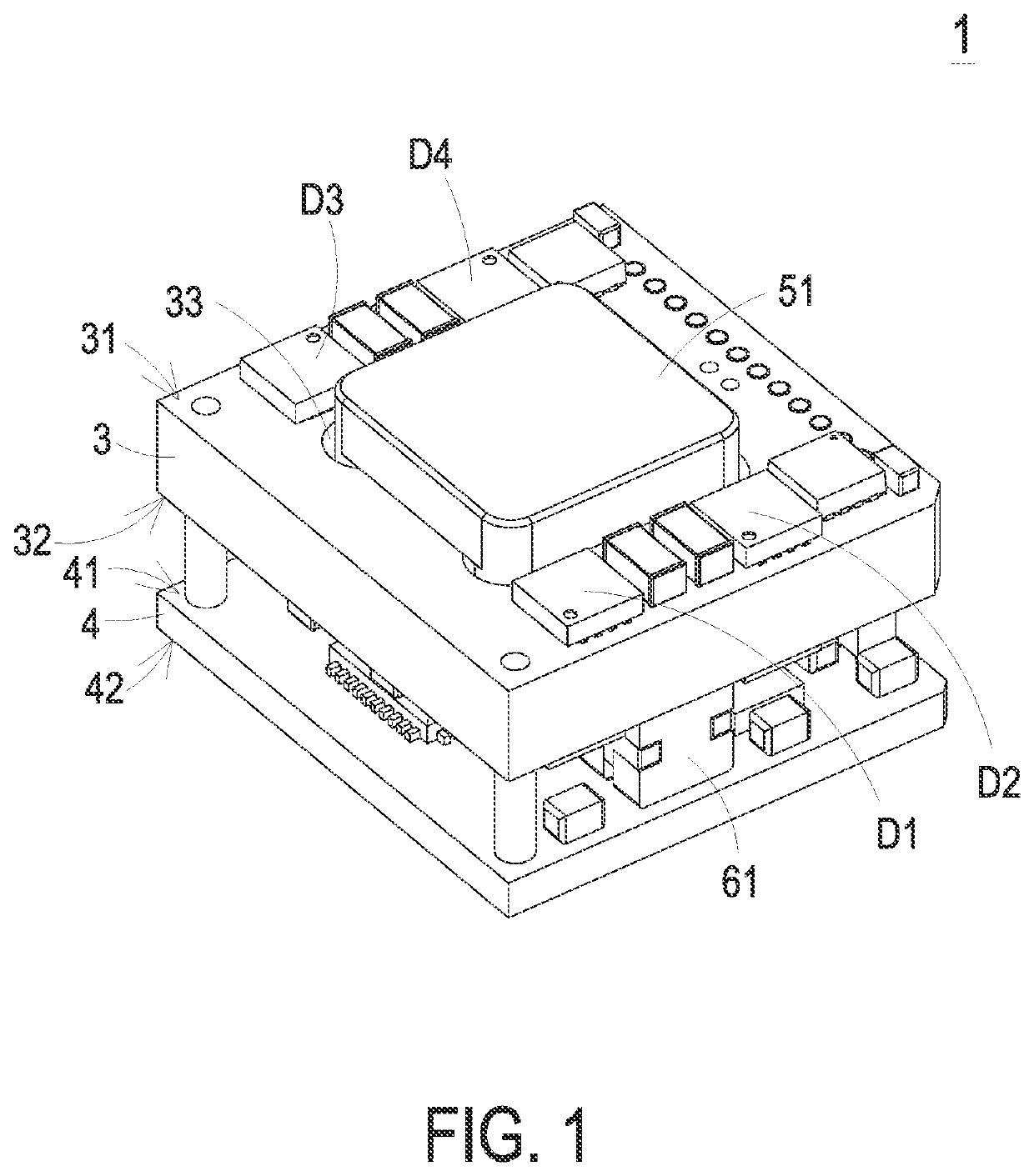
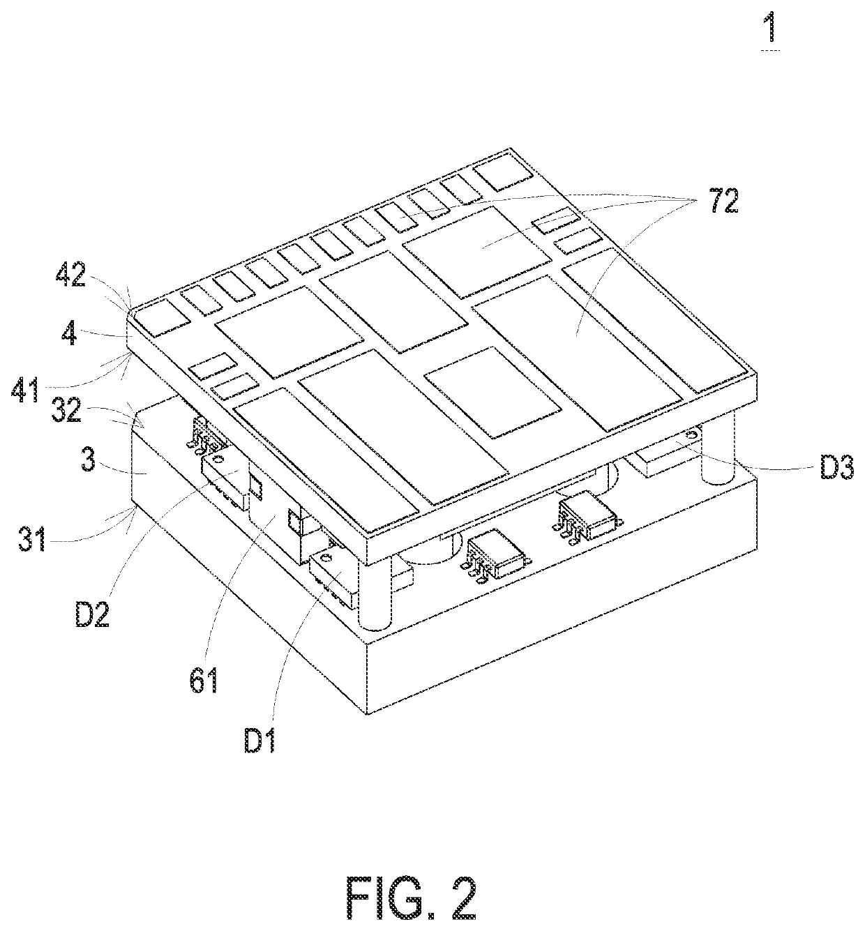
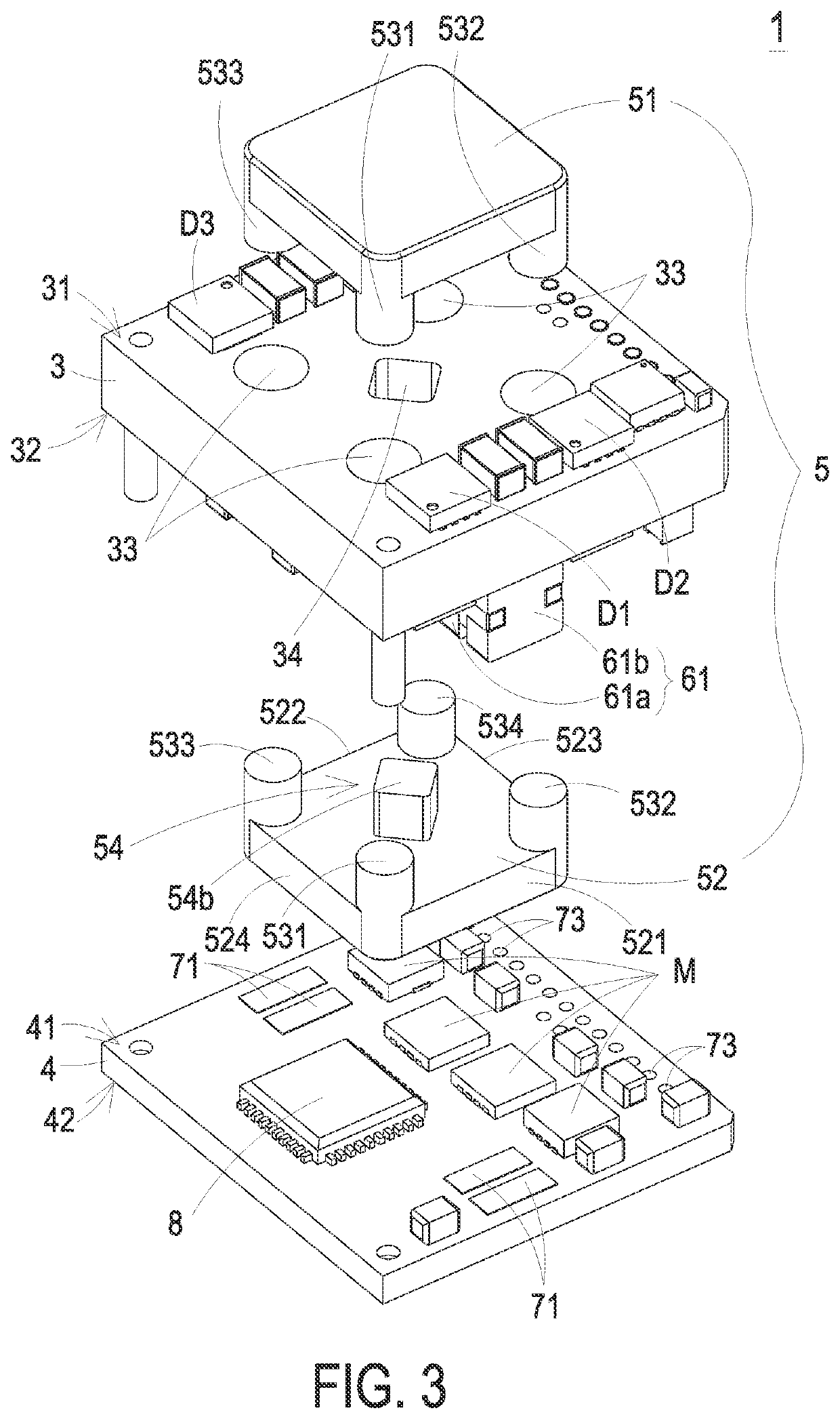
[0024]FIG. 1 is a schematic perspective view illustrating a power module according to an embodiment of the present disclosure. FIG. 2 is a schematic perspective view illustrating the power module as shown in FIG. 1 and taken along another viewpoint. FIG. 3 is a schematic exploded view illustrating the power module as shown in FIG. 1. FIG. 4 is a schematic exploded view illustrating the power module as shown in FIG. 1 and taken along another viewpoint. FIG. 5 is an equivalent circuit of the power module as shown in FIG. 1. FIG. 6 schematically illustrates the detailed circuitry structure of the equivalent circuit of the power mo...


PUM


Abstract

A magnetic assembly includes a magnetic core, four primary windings and four secondary windings. The magnetic core includes four lateral legs. The four primary windings and the corresponding secondary windings are magnetically coupled with each other, and the four primary windings and the corresponding secondary windings are wound on the corresponding lateral legs. The winding directions of the four secondary windings on the corresponding lateral legs are identical. A phase difference between a magnetic flux flowing through a specified lateral leg of the four lateral legs and a magnetic flux flowing through an adjacent lateral leg is any value in the range between 150 degrees and 210 degrees. A phase difference between the magnetic flux flowing through the specified lateral leg and the magnetic flux flowing through another adjacent lateral leg is any value in the range between 60 degrees and 120 degrees.

Description

CROSS-REFERENCE TO RELATED APPLICATION[0001]This application claims priority to China Patent Application No. 202010123504.8, filed on Feb. 27, 2020. This application also claims priority to China Patent Application No. 202011095569.2, filed on Oct. 14, 2020. The entire contents of the above-mentioned patent applications are incorporated herein by reference for all purposes.FIELD OF THE INVENTION[0002]The present disclosure relates to a magnetic assembly and a power module, and more particularly to a magnetic assembly with low cost, small volume and high power density and a power module with the magnetic assembly.BACKGROUND OF THE INVENTION[0003]With the rapid development of science and technology today, power modules are widely used in different fields, such as telephone communications, data centers, and supercomputers. In various fields, power modules are usually used to convert the received electric energy into a regulated voltage in order to power the related electronic devices. ...

Claims


Application Information

Patent Timeline
IPC IPC(8): H01F27/26H01F27/28H01F27/34H01F27/29H05K1/11
CPCH01F27/266H01F27/2804H01F27/34H05K2201/10015H05K1/111H05K2201/10053H05K2201/10189H01F27/29H02M1/00H02M3/33569H01F27/263H05K1/144H05K1/18H01F2027/2819H05K1/145H05K2201/10166H05K3/321H05K1/165H05K2201/086H05K2201/2036H05K1/181H05K3/3494H05K2201/10734
Inventor JIN, DALENG, YANGYANG, ZHONGWANGSU, QINGHUA
Owner DELTA ELECTRONICS INC
Why Eureka
Try Eureka