Medical endoscope with a cooling device for mounted electric components

a cooling device and endoscope technology, applied in endoscopes, medical science, surgery, etc., can solve the problems of affecting the operation, limiting the space available, and increasing the cost of endoscope caps, so as to facilitate the operation and facilitate manufacturing

Active Publication Date: 2019-03-12
INVENDO MEDICAL GMBH
View PDF16 Cites 0 Cited by
  • Summary
  • Abstract
  • Description
  • Claims
  • Application Information

AI Technical Summary

Benefits of technology

[0009]The fundamental idea of the invention is based on combining as many as possible or especially selected functional units in one integral component so as to save space for supporting and guiding means for the assembly of the individual functional units, wherein the saved space then can be used otherwise, for instance for more voluminous illumination means, a working channel having an enlarged diameter or the like. It is a side effect of this integral design that individual functional units such as the illumination can be moved further toward the distal end face of the endoscope head, where appropriate, so that the efficiency thereof may be improved without the power thereof having to be increased.
[0021]In other words, according to an aspect of the invention the illumination is integrated quasi in the end face of the sleeve. That is to say, the sleeve then does not only serve as protection cap for the incorporated functional units, but is also provided with a corresponding recess at the distal end face thereof or is substantially open at the distal end face so that the illumination can be inserted from the distal side into the sleeve and can be fixed in the latter. This has the advantage that an additional support for the illumination is dispensed with.

Problems solved by technology

This thermal energy further results in impairments of the optical means, especially of the usually heat-sensitive light sensor.
These supports further limit the space available which is quite limited anyway and render the manufacture of the endoscope cap more expensive.

Method used


Image

  • Medical endoscope with a cooling device for mounted electric components

Examples


Embodiment Construction

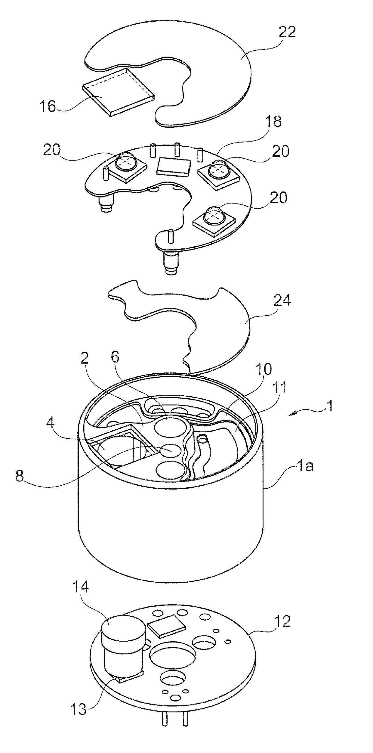
[0025]In accordance with the enclosed FIG. 1, an endoscope head according to a preferred embodiment of the invention has a cylindrical endoscope head sleeve (hereinafter simply referred to as sleeve) 1 which is adapted to be fixed to the distal end of a preferably flexible endoscope shaft (coloscope shaft) not shown in detail, as it is disclosed, for instance, in the state of the art according to U.S. Pat. No. 7,413,543 B2 mentioned in the beginning.

[0026]According to the invention, the sleeve 1 includes a cylindrical sleeve body 1a which at its distal axial end portion or end face has a radially inwardly extending support or a connecting base 2 having substantially pitch circle shape (triangular in top view) inter alia for a working channel, wherein in the present case the support 2 is formed (injection molded) integrally with the sleeve body 1a preferably of a plastic material.

[0027]In the support 2 a number of through-bores 4-8 are formed. In particular a central opening 6 is pro...


PUM


Abstract

An endoscope with a flexible endoscope shaft has an endoscope head arranged at its distal end. The endoscope head is a sleeve, open at both end faces. Functional units, such as an optical system, a working channel, an illumination and a cooling system for the illumination are accommodated in the endoscope head. The cooling system has a heat exchanger integrally formed with the sleeve in the latter which forms a closed cooling chamber for generating a coolant flow. The illumination, which is in the form of an external conductor plate supporting an illumination means, is arranged adjacent to the distal end wall of the heat exchanger, to discharge thermal energy via the end wall of the heat exchanger to the coolant flow. The external conductor plate is mechanically supported on, or has only a minimum distance from, the heat exchanger end wall.

Description

CROSS-REFERENCE TO RELATED APPLICATIONS[0001]This application is entitled to benefit of a right of priority under 35 USC § 119 from German patent application DE 10 2011 055 526.9, which was filed on 18 Nov. 2011, the content of which is incorporated by reference as if fully recited herein.TECHNICAL FIELD[0002]The present invention relates to a medical endoscope having electric components being mounted in the endoscope head thereof that are cooled by means of an internal cooling device, and in particular to an endoscope in accordance with the preamble of claim 1.BACKGROUND OF THE ART[0003]Electronic / electric components such as light-sensitive sensors (CMOS chips), light emitting diodes (LED) etc. have been increasingly employed in medical devices, for example in endoscopic devices. Especially endoscopes / coloscopes have at the distal end of a flexible endoscope shaft a so called endoscope head in which a number of functional units such as, inter alia, an optical means comprising a len...

Claims


Application Information

Patent Timeline
Patent Type & Authority Patents(United States)
IPC IPC(8): A61B1/12A61B1/04A61B1/06A61B1/00A61B1/05
CPCA61B1/0676A61B1/128A61B1/0011A61B1/05
Inventor DILLINGER, ANJA KATRINSCHUETZ, GUENTER WILHELMSCHNUERER-PATSCHAN, CHRISTOPH
Owner INVENDO MEDICAL GMBH
Why Eureka
Try Eureka