
Switching AC/DC power supply system with 10MHz time base

Active Publication Date: 2021-08-31
HONG LIU CO LTD
View PDF6 Cites 0 Cited by
  • Summary
  • Abstract
  • Description
  • Claims
  • Application Information

AI Technical Summary

Benefits of technology

The present invention provides a switching AC / DC power supply system with a 10 MHz time base. This allows multiple AC / DC power supplies to be synchronized, reducing electromagnetic interference, output ripple rate, and frequency errors between the power supplies. The system achieves a high-quality AC / DC power source with low output ripple rate and low EMI noise. The time base generator of the master is inputted to the time base processing circuit of the slave through the connection cable, resulting in a synchronized time base.

Problems solved by technology

If the time base is not accurate enough, it is a major source of “jitter”.
If the demand for large capacity is achieved with a single power supply, the cost is too high.
When multiple power supplies are connected in parallel and if the time bases of the power supplies cannot be synchronized, it will cause errors in the switching frequency to bring electromagnetic interference and resonance.

Method used


Image

  • Switching AC/DC power supply system with 10MHz time base
  • Switching AC/DC power supply system with 10MHz time base
  • Switching AC/DC power supply system with 10MHz time base

Examples


first embodiment

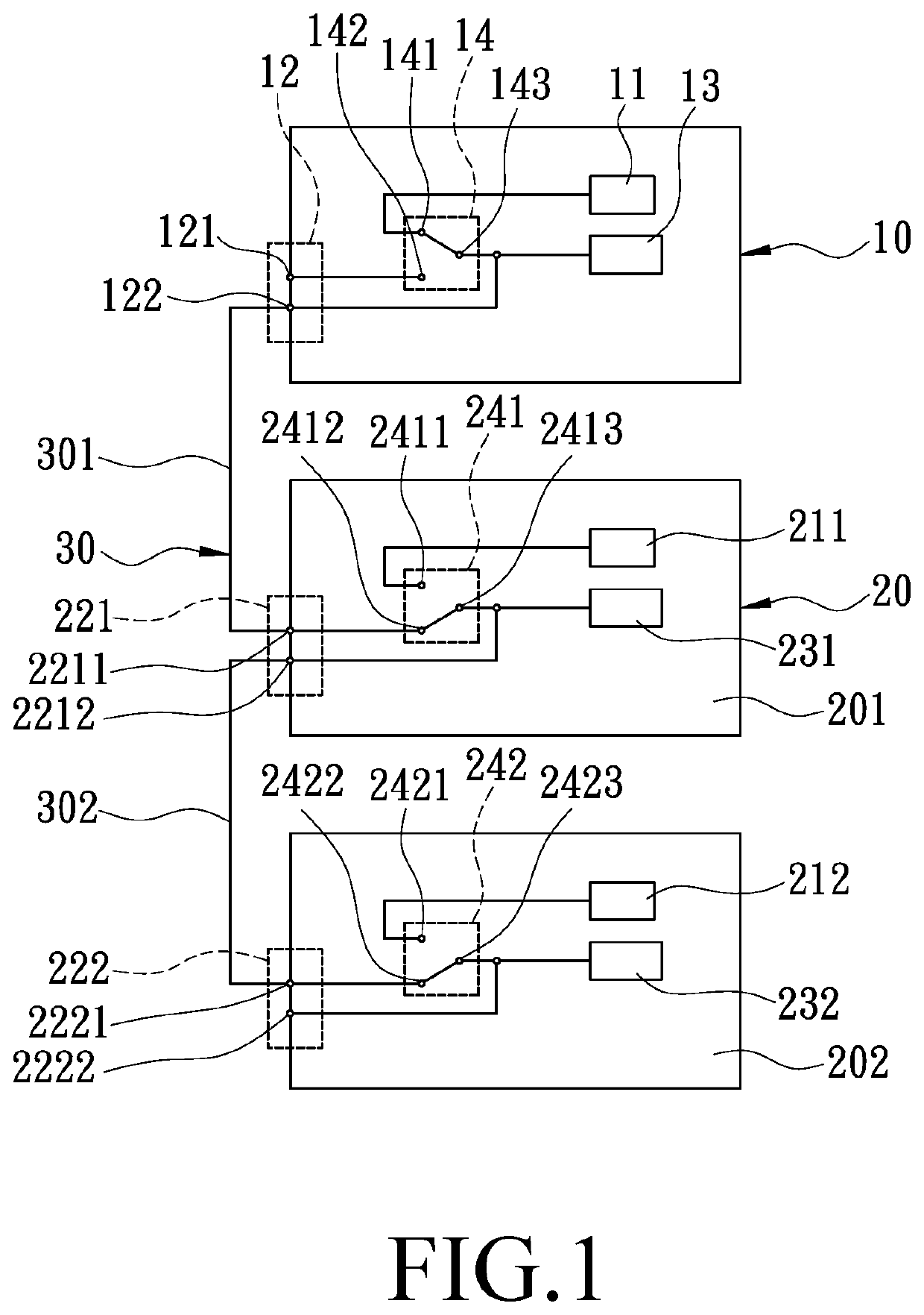
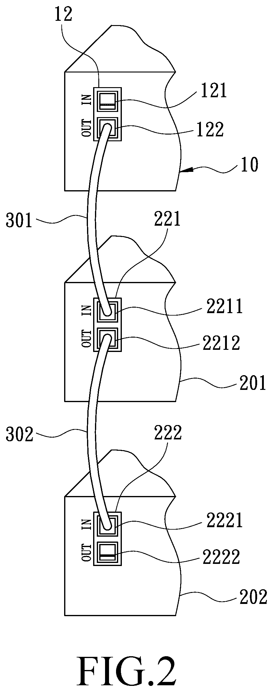
[0021]The selector switch 14 is a manual switch. One end of the selector switch 14 is provided with a first contact 141 and a second contact 142, and the other end of the selector switch 14 is provided with a third contact 143. The third contact 143 is selectively connected to the first contact 141 to form a path, or the third contact 143 is selectively connected to the second contact 142 to form a path. The first contact 141 is connected to the time base generator 11. The second contact 142 is connected to an external port. In the present invention, when the selector switch 14 has no external connection at the second contact 142, the third contact 143 is selectively connected to the first contact 141.

[0022]The time base processing circuit 13 is connected to the third contact 143 of the selector switch 14 to receive the time base of the time base generator 11 or an external time base and to perform frequency division, so as to provide the required frequency for each electronic compo...

fifth embodiment

[0048]FIG. 6 and FIG. 7 illustrate the present invention. The fifth embodiment is substantially similar to the first embodiment with the exceptions described hereinafter. The system comprises a master 60, a first slave 701, a second slave 702, and at least one connection cable 30.

[0049]The master 60 has a port 62. The port 62 is a common port for input and output, and the port 62 is a BNC port. But, this is only an embodiment, not a limitation on the implementation of the present invention. The port 62 may be a SMA, BNC, or optical fiber port. A selector switch 64 includes a first contact 641, a second contact 642, a third contact 643, and a fourth contact 644. The first contact 641 is connected to a time base generator 61. The third contact 643 is connected to a time base processing circuit 63. The fourth contact 644 is connected to the port 62. Both the third contact 643 and the fourth contact 644 are selectively connected to the first contact 641 to form a path, or both the third...


PUM


Abstract

A switching AC / DC power supply system with a 10 MHz time base includes a master and at least one slave, each of which has a time base generator, and the time base generators can provide a time base of 10 MHz. Wherein the slave has a selector switch, and when the master is coupled to the slave, the slave can obtain the time base from the time base generator of the master through the selector switch, thereby enabling the time base of the slave is fully synchronized with the master and improving the power output quality of the switching AC / DC power supply system.

Description

FIELD OF THE INVENTION[0001]The present invention relates to an AC / DC power supply, and more particularly to a switching AC / DC power supply system with a 10 MHz time base.BACKGROUND OF THE INVENTION[0002]AC / DC power supplies are categorized into linear AC / DC power supplies and switching AC / DC power supplies according to their working principles and design structures. The basic structure of a linear AC / DC power supply includes a linear amplifier with the first quadrant being DC and the first and fourth quadrants being AC and a bipolar DC power supply. If it involves bidirectional DC, they are the first and second quadrants. Linear amplifiers are generally categorized into A, B, AB, etc., and use the linear region of power components. The basic working quadrant of the switching AC / DC power supply is the same as that of the linear AC / DC power supply, except that the amplifier adopts a D amplifier. The D amplifier as a switching working mode has the advantage of high efficiency. With th...

Claims


Application Information

Patent Timeline
IPC IPC(8): H02M7/02H02J4/00
CPCH02J4/00H02M7/02
Inventor LIN, MU-CHUN
Owner HONG LIU CO LTD
Learn More