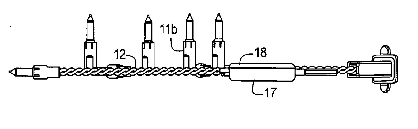
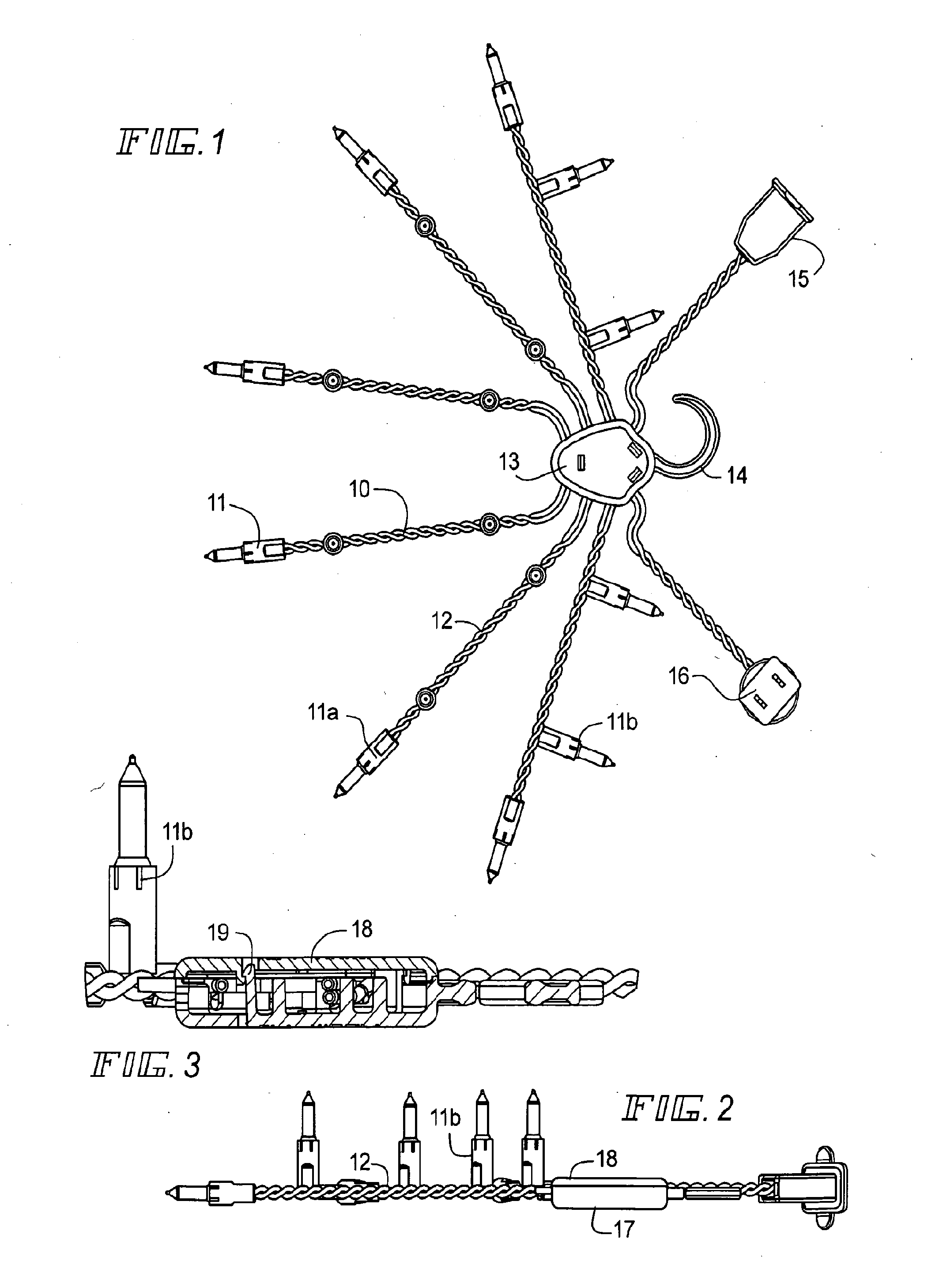
[0057]With reference to the accompanying drawings and particularly to FIGS. 1-3, a strand 10 of lamps 11 are arranged on electrical wires 12, and trained through a hub or spreader 13, which preferably may have a hook 14 for engaging a tree limb or other structure. A number of strands 10 may be bundled together through the hub 13, which pre-separates the wires. The hub may be used to stabilize the strand. A plug 15 and socket 16 for connecting the bundle of strands 10 to another bundle or strands and/or to a source of power may also be provided and arranged connected to the wires 12 through the hub 13 The lamps may be oriented relative to the wires 12 and hub 13, so that some lamps 11a are extended in the plane of the wires 12 and other lamps 11b are arranged in a plane perpendicular to the wires 12.
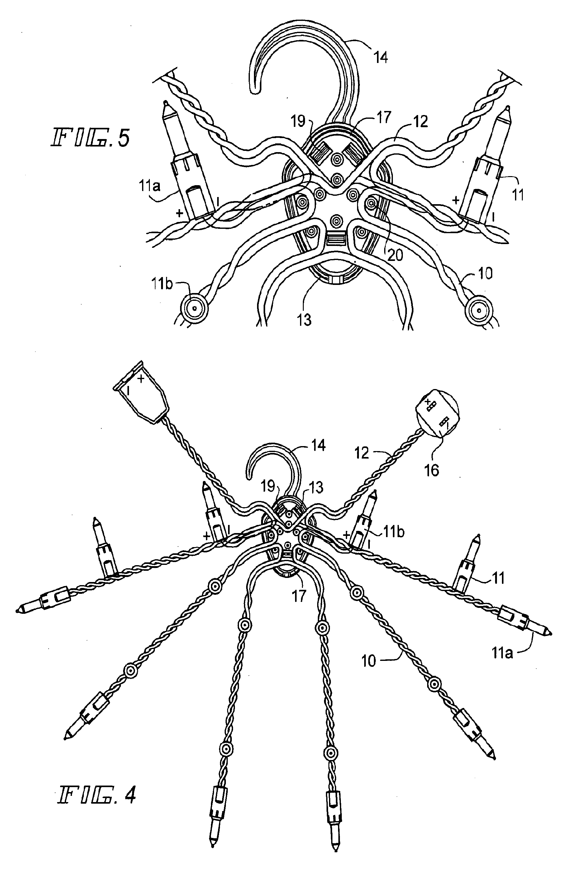
[0058]As shown in FIG. 3, the hub 13 may comprise a body 17 and a cover 18, which can be snapped together by means of barbed teeth 19. With reference to FIGS. 4 and 5, the body 17 may also have a series of upstanding ribs 20, which may be used to train and pre-separate the wires 12 of each strand 10 in a selected direction through the hub 13 in a manner so the wires 12 of each strand and those connecting the plug and socket lay in a predetermined selected position.
[0059]Alternatives to the hub and related structure shown in FIGS. 1-5 are depicted in FIGS. 6 and 7. In FIG. 6, the modified hub 23 comprises a molded piece which has the wires 12 secured therein. In FIG. 7, twisted plastic fastener connections 24 perform the function of the hub 13 to properly orient the wires 12 and lamps 11.
[0060]FIGS. 8-10 depict details of the preferred hub 13, preferably made of plastic dielectric insulating material. The body 17 and its cover 18 may be pendant shaped with beveled sides 25 for easy handling, and of a size to accommodate the electric wires 12 in a recess 26 formed by the body 17 and cover 18 when closed. The ribs 20 are formed on the underside 27 of the body 17 and are of a size to reach the inside wall of the cover 18, so that the wires 12 when arranged in the recess 26 will stay in a selected position. The barbed teeth 19 are upstanding on the body 17 and may be snap engaged over cooperating teeth 28 into apertures 29 in the cover 18; and preferably there are multiple sets of these members to close the body 17 and cover 18, but they may be selectively manipulated to open the recess 26 for adjustment of the wires 12. The hook 14 preferably has a longitudinally extending central reinforcement 30 which permits it to be flexible without breaking. Preferably, the hook 14 and body 17 and cover 18 are molded from thermoplastic insulating materials, so that they protect the wires, even under stress when the hook 14 is assembled on a limb L of a tree or other member.
[0061]Alternate hub forms are shown in FIGS. 11-13. In FIG. 11, the hook 33 has a loop 34 through which each of the strands 10 extend; and in FIG. 12, each of the strands 10 extend from an apertured hook 43. In FIG. 13, the central restraining means for holding the bundle of strands 10 together is a sleeve 53 which is secured to or wrapped around the strands 10. In both the FIGS. 11 and 13 embodiments, during manufacture, the strands 10 may be extended on one side of the hook 33 or sleeve 53, to accommodate the length of a branch B as desired on which it may be mounted or to accomplish a design conceived of by the trimmer.
[0062]In each case, the hub or its equivalent 13 or 23 or 33 or 43 or 53 is removably secured around a limb L or post P and the strand(s) are extended outwardly substantially horizontally therefrom along a branch B or other structure. To remove the strand 10 from its limb L or post P, the hook-like member or its equivalent is merely backed up and the strand 10 is pulled from the branch B or the like. The bundle of strands 10 can be suspended by the hook-like member from a peg or rolled up for storage until its reused.
[0063]In FIGS. 14-16, a trimmed tree T is shown. With reference to FIG. 14, each strand 10 is connected by a hook 14 or the like from the trunk-like post P or a limb L and encircles the tree T outwardly from its center. Strands !0 may be connected together by means of their respective plugs and sockets, and a plug 15 at the end of a strand 10 may be exposed for connection to a source of power.
[0064]In FIG. 15, a branch B with the wires 12 of a strand 10 wound around it is shown, taken from the circle displayed in FIG. 14. Above and part of FIG. 15 is a sketch showing the electric wires 10 which may be interwoven with a soft plastic tie 50. The lamps 11 may be oriented as the decorator desires. FIG. 16 shows a modification of a strand 10 where the soft tie 50 or tape my be interconnected adjacent a lamp 11, so that the lamp may be bound and secured in a selected position on the limb L.
[0065]FIG. 17 illustrates another possibility using the novel structure and method disclosed in this application. The lamps 11 in this modification are arranged in lamp holders 51 or similar ornaments and are oriented to stand upward when arranged on a tree or other connected surface. In this embodiment decorative members such as small toys or dolls or other ornaments may be connected to a strand 10 and oriented like the lamp holders 51 in a selected predetermined position on the wires 12, with or without lamps. The arrangement of these ornaments may be predetermined on a strand before the strand 10 is positioned on a tree or other surface. The strand 10 need only be extended outwardly from the hub 13 and hook-like member 14 on a tree trunk T or a post to place the ornament or any special decoration in proper position.
[0066]In FIGS. 18 and 19, a strand 10a is shown connected to another strand 10b by means of the socket 16 and plug 17 arrangements previously describer. The strands 10 may be extended vertically along a tree trunk T or post, and the lamps 11 are aligned upright on a limb L or branch B. Each strand 10a has a hook-like member which may be engaged on the trunk T or post, to fully extend the stand in a vertical direction. A plug on the extreme end of a strand may be connected through a extension cord E or the like to a source of power. Likewise, as shown in FIG. 19, multiple light strands 10 may be removably secured on the trunk T or post and extended outwardly horizontally from the trunk T, with one part of the strand 10 connected to trunk T. To remove the strands from the trunk T, one need only disconnect the hook-like member 14 and pull the wires 12 and connected lamps 11 toward the hook-like member 14, where they can be conveniently bundled without tangling.
[0067]A typical circuit for a strand 10 is shown in FIG. 20. Note that each strand has wires 12 which connect the lamps 11 in series and the sets in parallel. This arrangement also permits multiple strands to be connected together through each socket 15 and plug/socket 16 of successive strands.
[0068]FIGS. 21 and 22 show a modified electrical arrangement where a two pole 52a and 52b circuit breaker or limit switch 52, which may have an optional ground 57. So long as the breaker or limit switch 52 is closed, power will flow through the wires 12 to the lamps 11. If there is a short or overload, the switch or circuit breaker 52 will open and power will be shut down before there is a dangerous overload or a fire hazard. The plug 15 or socket 16 can be provided with an exterior connection button 56 to the breaker or switch 52, so that a open switch can be closed by merely pressing the button once the cause of the overload or short is eliminated. Such an arrangement permits joining multiple strands 10 and the use of strands without danger of overload or fires or other electrical hazards.
[0069]As shown in FIG. 23, the wire configuration comprises six strands 10 of lamps 11 and two lengths of connecting wires 12, one length 60 having a male plug 61 and the other length 62 having a female socket 63, and these strands are secured together at their centers by a novel modified hook 64, discussed hereafter. The strands may be assembled into kits with strands 10 of different lengths and numbers of bulbs 11 for selected different applications. For example, when trimming a typical Christmas tree, a shorter length of strand 10 can be provided for the top of the tree and longer lengths of strands 10 can be used on the girth of the tree, and this arrangement makes for a neater assembly. The plug 61 and socket 63 of a strand 10 may be trained along the central limb of the tree, instead of dangling over the circumference, and the strand on each horizontal level of the tree may be electrically connected to an adjacent level and the lower level strand maybe connected to a source of power so that the connecting wires are not visible from the periphery of the tree. The novel modified hook 64 shown in FIG. 24 is preferably molded from bendable plastic material, and comprises a hook portion 65 for connection to a limb, and a section 66 for encircling a bundle of strands 10 at any selected point along the length of strands, depending upon the surface to be decorated. This hook section 66 comprises a length of material preferably having a preformed radius, and has a barb 67 at one end and a receiving clip 68 at its other end, so that the barb may be connected to the clip for encircling a bundle of strands 10. When storing the strands 10 for the next year's use, the hook may be removed from the limb and the barb 67 may be released and removed from the clip 68, so that the strands may be conveniently stored and reused as desired, with minimum risk to the bulbs 11 and the wires 12.
[0070]Within recent years, pre-lit Christmas trees and similar pre-lit decorations have become popular, but on occasion one or more of the pre-lit lights require repair. In such an event, strands embodying the present invention may be utilized as a repair kit for such pre-lit devices. Such strands easily blend into the pre-lit device in a neat and attractive fashion.
[0071]While the novel decorative strands embodying the invention and the inventive method has been show in considerable detail and with many alternatives, it should be understood that other alternatives are possible without departing from the scope or spirit of the invention, and, accordingly, it is desired that the invention should not be limited to the exact construction, arrangement of parts and processes described.