Method and apparatus for determining a corrected monitoring voltage

a technology of monitoring voltage and measurement method, applied in the field of power systems, can solve the problems of increasing the cost of solar panels, reducing the efficiency of solar energy generation,

Active Publication Date: 2010-08-05
ENPHASE ENERGY
View PDF23 Cites 117 Cited by
  • Summary
  • Abstract
  • Description
  • Claims
  • Application Information

AI Technical Summary

Problems solved by technology

Due to the high cost of installation, solar panels were not an economical choice for generating power unless no other power options were available.
However, the worldwide growth of energy demand is leading to a durable increase in energy cost.
In addition, it is now well established that the fossil energy reserves currently being used to generate electricity are rapidly being depleted.
In some circumstances, the measured voltage at the inverter may exceed the required voltage range although the voltage at the PCC remains within the required range, resulting in the inverter unnecessarily shutting down and thereby reducing energy production.
Additionally, as the inverter ceases power production and the voltage at the inverter is reduced to acceptable levels, the inverter once again activates and begins producing power, resulting in a continued oscillation that negatively impacts power production.

Method used


Image

  • Method and apparatus for determining a corrected monitoring voltage
  • Method and apparatus for determining a corrected monitoring voltage
  • Method and apparatus for determining a corrected monitoring voltage

Examples


Embodiment Construction

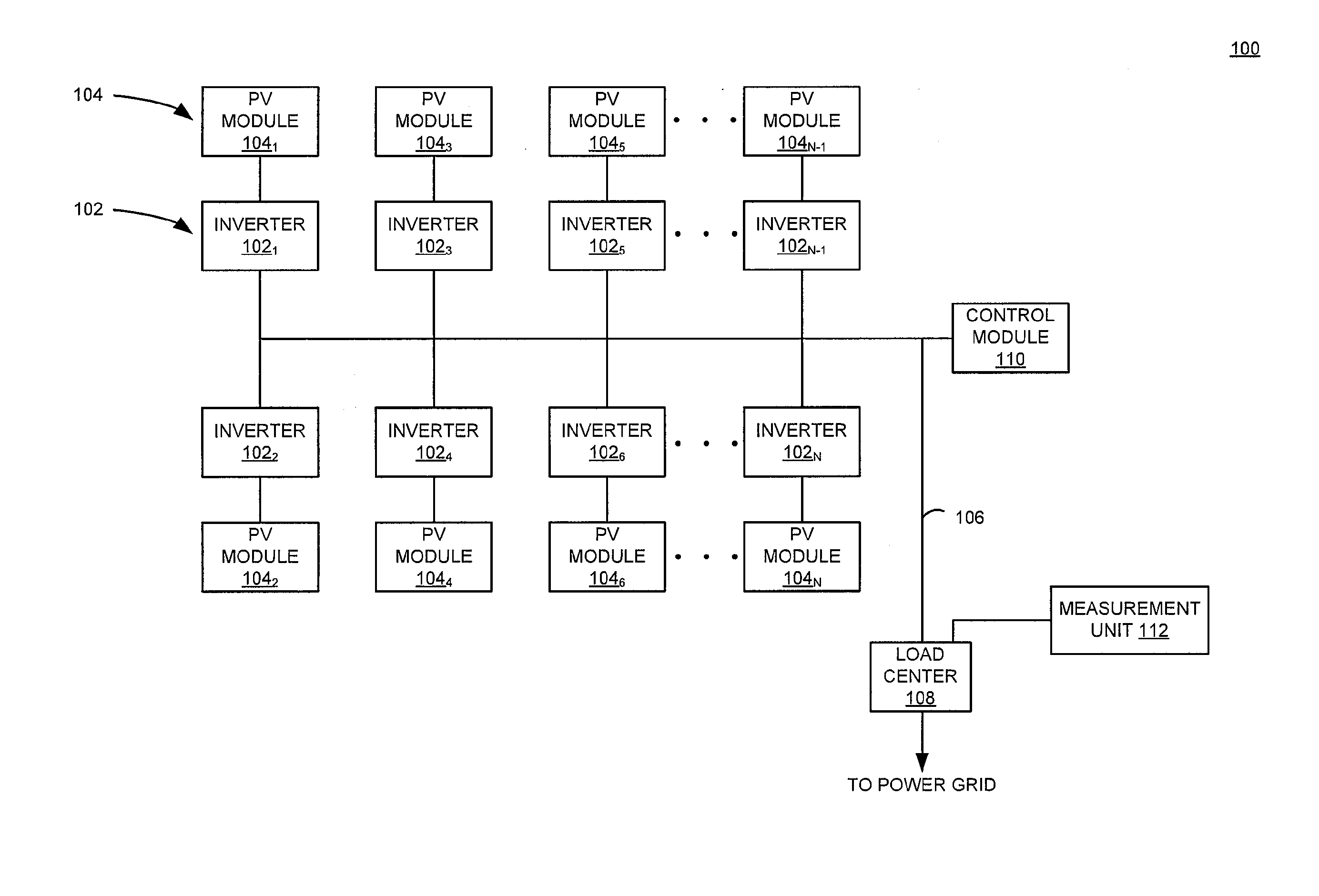
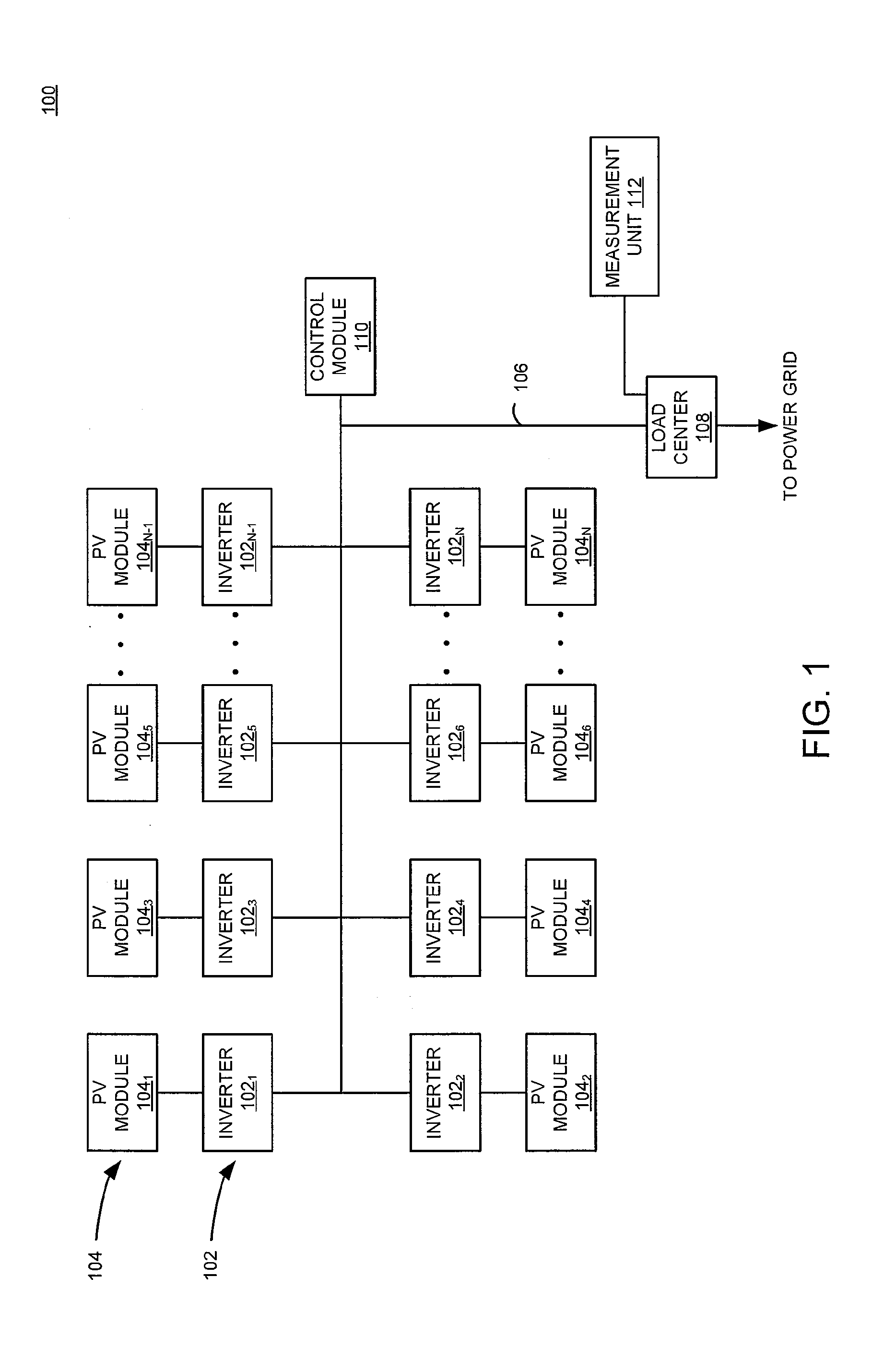
[0016]FIG. 1 is a block diagram of a system 100 for distributed generation (DG) in accordance with one or more embodiments of the present invention. This diagram only portrays one variation of the myriad of possible system configurations. The present invention can function in a variety of distributed power generation environments and systems.

[0017]The system 100 comprises a plurality of inverters 1021, 1022 . . . 102n, collectively referred to as inverters 102, a plurality of PV modules 1041, 1042 . . . 104n, collectively referred to as PV modules 104, an AC bus 106, and a load center 108.

[0018]Each inverter 1021, 1022 . . . 102n is coupled to a PV module 1041, 1042 . . . 104n, respectively. In some embodiments, a DC-DC converter may be coupled between each PV module 104 and each inverter 102 (e.g., one converter per PV module 104). Alternatively, multiple PV modules 104 may be coupled to a single inverter 102 (i.e., a centralized inverter); in some such embodiments, a DC-DC convert...


PUM


Abstract

A method and apparatus for determining a corrected monitoring voltage, at least a portion of the method being performed by a computing system comprising at least one processor. The method comprises generating power at a first location; monitoring the generated power by measuring a first voltage proximate the first location; measuring a second voltage proximate a second location, the first and the second locations electrically coupled; and determining, based on the measured second voltage, a corrected monitoring voltage to compensate the measured first voltage for a distance between the first and the second locations.

Description

CROSS-REFERENCE TO RELATED APPLICATIONS[0001]This application claims benefit of U.S. provisional patent application Ser. No. 61 / 206,891, filed Feb. 5, 2009, which is herein incorporated in its entirety by reference.BACKGROUND OF THE INVENTION[0002]1. Field of the Invention[0003]Embodiments of the present disclosure generally relate to power systems and, more particularly, to a method and apparatus for determining a corrected monitoring voltage.[0004]2. Description of the Related Art[0005]Solar panels have historically been deployed in mostly remote applications, such as remote cabins in the wilderness or satellites, where commercial power was not available. Due to the high cost of installation, solar panels were not an economical choice for generating power unless no other power options were available. However, the worldwide growth of energy demand is leading to a durable increase in energy cost. In addition, it is now well established that the fossil energy reserves currently being...

Claims


Application Information

Patent Timeline
Patent Type & Authority Applications(United States)
IPC IPC(8): H02H7/122G01R19/00H02H7/00H02J3/00H02M7/44
CPCH02J3/383H02J3/386H02J3/382Y02E10/763H02M7/44Y02E10/563H02J2300/28H02J2300/20H02J2300/24H02J3/381Y02E10/56Y02E10/76H02J3/46
Inventor FORNAGE, MARTINDARGATZ, MARV
Owner ENPHASE ENERGY
Why Eureka
Try Eureka