Packet relay system and wireless node

a relay system and packet technology, applied in the field of packet relay systems, can solve the problems of difficult to calculate the correct link cost, temporary link disconnection, and insufficient link cost calculation method of routing according to the conventional many to one scheme, so as to achieve the appropriate link cost, quickly transmit packets to the destination node, and avoid increasing the amount of information communicated in the network

Active Publication Date: 2010-08-05
OKI ELECTRIC IND CO LTD
View PDF12 Cites 77 Cited by
  • Summary
  • Abstract
  • Description
  • Claims
  • Application Information

AI Technical Summary

Benefits of technology

[0020]The packet relay system according to the invention can calculate an appropriate link cost even when link conditions have been changed and thus can establish an upstream path to a sink node without increasing the amount of information communicated in a network.
[0021]In addition, the packet relay system accor

Problems solved by technology

However, the link cost calculation method used for routing according to the conventional many to one scheme is not definite.
However, this has a problem in that it is difficult to calculate a correct link cost since an LQI obtained when an RREQ command is received varies.
Especially, when nodes are installed over a wide area such as the outdoors, temporary link disconnection may occur, changing link conditions, due to an obstacle such as a person and a car passing between the nodes.
Therefore, there is a problem in that the amount of information communicated in the network increases and the use efficiency of

Method used


Image

  • Packet relay system and wireless node
  • Packet relay system and wireless node
  • Packet relay system and wireless node

Examples


first embodiment

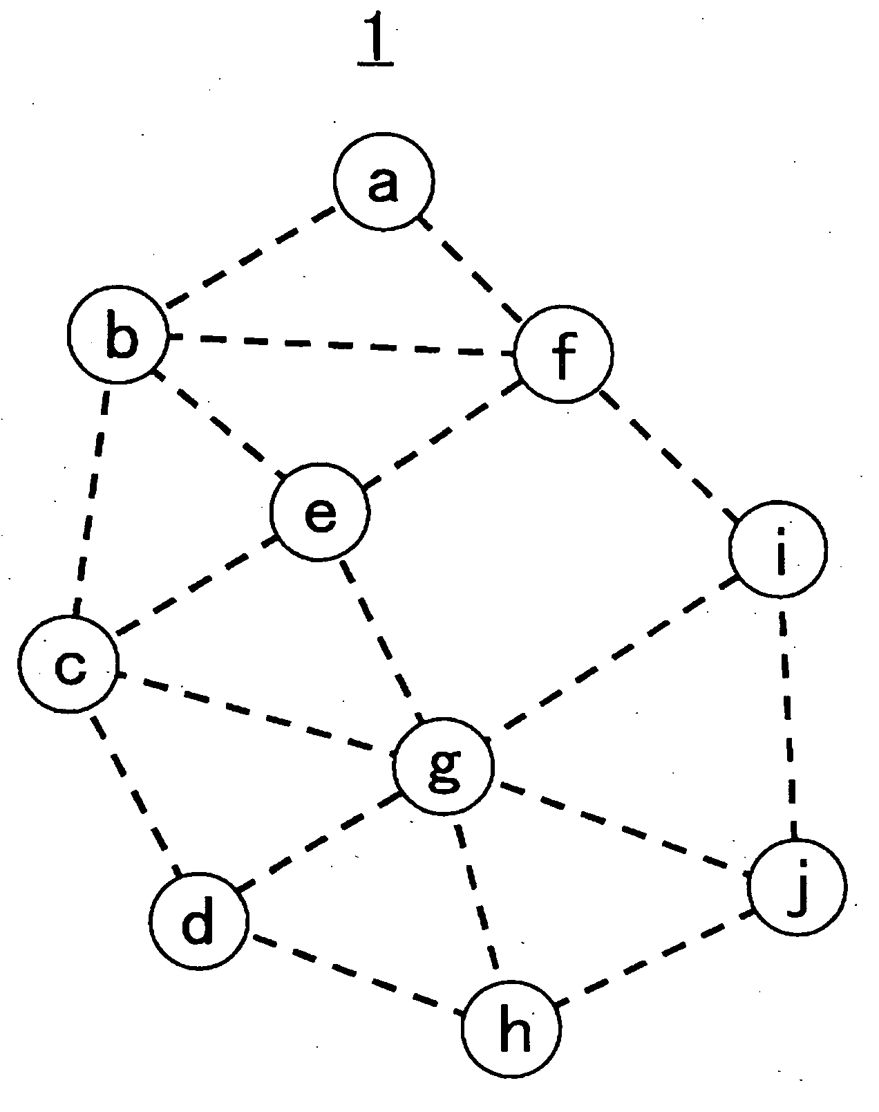
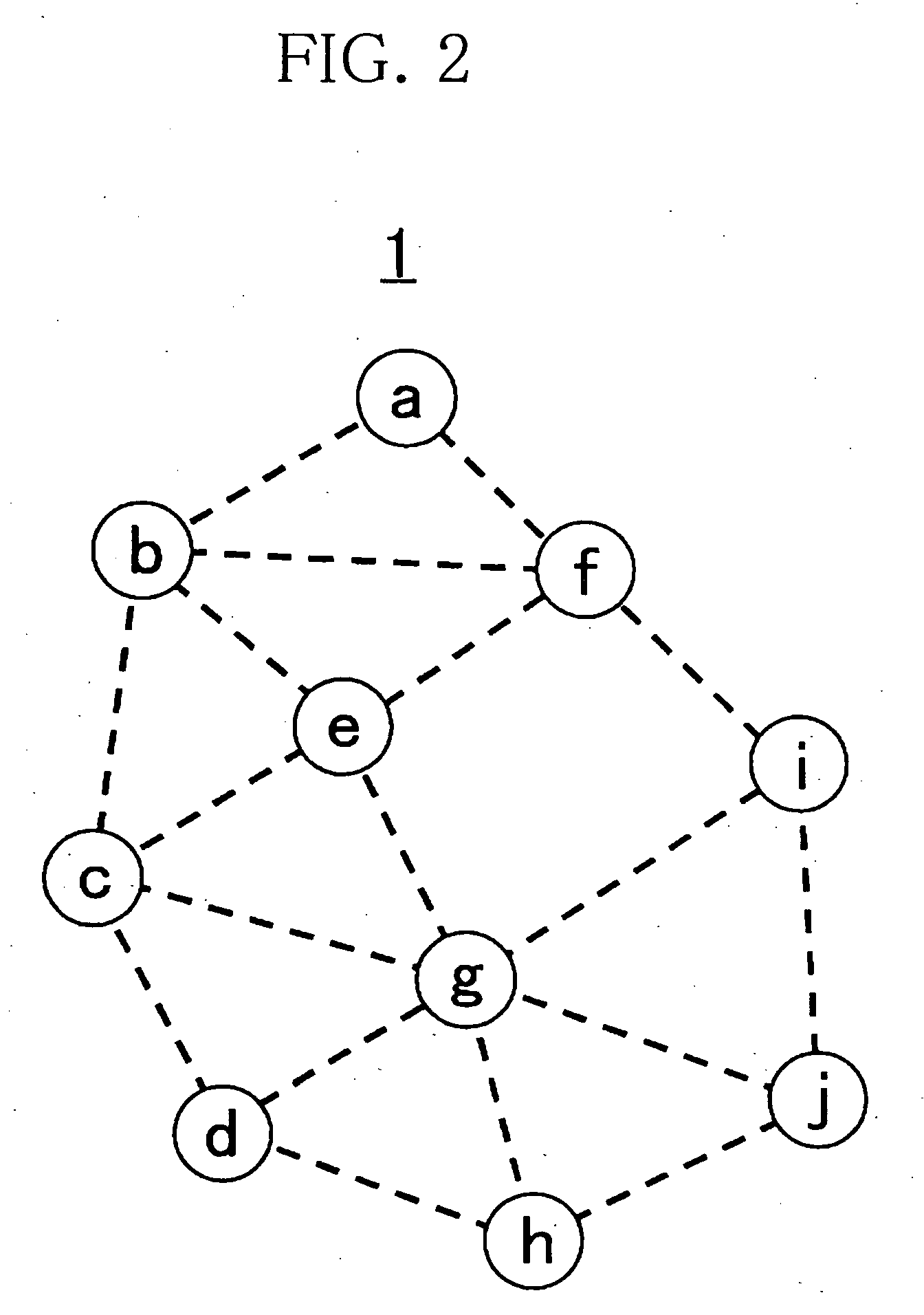
[0049]FIG. 2 is a schematic diagram illustrating a packet relay system 1 according to this embodiment. The packet relay system 1 is, for example, a wireless sensor network and includes a node a which is a sink node and nodes b to j which are sensor nodes. Each of the nodes a to j can exchange a packet with an adjacent node through wireless communication. Nodes that are connected by dotted lines in FIG. 2 can exchange packets with each other. For example, the node a can exchange packets with the nodes b and f. In the packet relay system 1, for example, sensor data generated at each of the nodes b to j is aggregated at the node a.

[0050]FIG. 3 is a block diagram illustrating a configuration of the node b according to this embodiment. Each of the nodes a and c to j has the same configuration as that of the node b.

[0051]The node b includes an antenna 101, an amplifier 102, a wireless signal transmitting and receiving unit 103, a packet receiving unit 104, a relay processing unit 105, a r...

second embodiment

[0100]FIG. 12 is a block diagram illustrating a configuration of the node b according to the second embodiment. Each of the nodes a and c to j has the same configuration as that of the node b. The node b includes a packet aggregation unit 110 in addition to the components of the node b of the first embodiment.

[0101]When it is determined that the relay processing unit 105 has received an RREC packet from one of the adjacent nodes, the packet aggregation unit 110 holds the packet until a predetermined transmission time is reached and, when it is determined that the relay processing unit 105 has received an RREC packet from an adjacent node other than the one adjacent node before the predetermined transmission time is reached, the packet aggregation unit 110 generates a new RREC packet (hereinafter referred to as an “aggregate packet”) which aggregates addresses of these RREC packets and causes the packet transmitting unit 109 to relay the aggregate packet to a relay destination adjace...

third embodiment

[0121]FIG. 16 is a block diagram illustrating a configuration of the node c according to the third embodiment. Each of the nodes a, b, and d to j has the same configuration as that of the node c. The node c includes a 2-hop adjacent node table 111 in addition to the components of the node b of the first embodiment.

[0122]FIG. 17A illustrates an example of the routing table 106 of the node c. FIG. 17B illustrates an example of the 2-hop adjacent node table 111 of the node c. The node c not only includes the same routing table 106 as that of the first embodiment but also includes the 2-hop adjacent node table 111. An address of each first hop node and an address of each second hop node are stored in the 2-hop adjacent node table 111. Here, the first hop node is a node that is adjacent to the node c and the second hop node is a node that is adjacent to the first hop node and is not adjacent to the node c. For example, the nodes b, e, d, and g are first hop nodes of the node c and the no...


PUM


Abstract

A packet relay system in which each node calculates a link cost of each adjacent node based on an arrival rate of a packet from each adjacent node, acquires an accumulated value of a link cost calculated by each node in a range of nodes from a sink node for each adjacent node, calculates, for each adjacent node, a path cost of the one adjacent node by adding the link cost calculated to the accumulated value, and relays a data packet to one adjacent node selected from among nodes adjacent to the node based on a path cost of each adjacent node. This enables establishment of an upstream path to a sink node without increasing the amount of communication in a network.

Description

BACKGROUND OF THE INVENTION[0001]1. Field of the Invention[0002]The present invention relates to a packet relay system including a plurality of nodes that relay a data packet to each other.[0003]2. Description of the Related Art[0004]A multihop wireless network which includes a plurality of wireless nodes, each having a packet relay function, and in which adjacent wireless nodes relay a packet to each other is known in the art. Through sequential relay of packets between wireless nodes, each wireless node can transmit a packet to a wireless node that is out of radio arrival range of the node.[0005]A routing protocol for determining a next wireless node, to which a packet is to be transmitted, from a destination address is needed in order to relay the packet to a desired wireless node. For example, routing protocols employing a variety of schemes such as a cluster tree routing scheme which requires no routing table by employing an address allocation method, an Ad Hoc On-Demand Distan...

Claims


Application Information

Patent Timeline
IPC IPC(8): H04B7/14H04L45/24
CPCH04B7/2606H04B7/155
Inventor NOZAKI, MASANORIYANAGIHARA, KENTAROUKUBO, YUKI
Owner OKI ELECTRIC IND CO LTD
Why Eureka
Try Eureka