Quantitative differential interference contrast (DIC) devices for computed depth sectioning

a technology of computed depth sectioning and contrast, applied in computing, phase-affecting property measurement, instruments, etc., can solve the problems of phase variation not being easily disentangled from amplitude (intensity) variation, and conventional dic devices have several limitations

Active Publication Date: 2010-08-05
CALIFORNIA INST OF TECH
View PDF74 Cites 36 Cited by
  • Summary
  • Abstract
  • Description
  • Claims
  • Application Information

AI Technical Summary

Benefits of technology

[0056]In general, quantitative DIC devices of embodiments of the invention provide advantages because they can separately measure the amplitude and phase gradient of an image wavefront in two orthogonal directions. With this information, the quantitative DIC device has sufficient data to numerically reconstruct an image wavefront and propagate it to other planes.

Problems solved by technology

However, conventional DIC devices have several limitations.
One major limitation is that conventional DIC devices translate phase variations into amplitude (intensity) variations.
Therefore, phase variations cannot be easily disentangled from amplitude (intensity) variations that arise from absorption and / or scattering by an object.
In other words, conventional DIC devices do not distinguish between the effects of absorption and phase variation.
As a consequence of this entanglement of amplitude and phase information and nonlinear phase gradient response, conventional DIC devices are inherently qualitative and do not provide quantitative phase measurements
Another limitation of conventional DIC devices is that they use polarized light and depend on the polarization in their phase-imaging strategies.
Since polarized light must be used, conventional DIC devices generate images of birefringent objects (e.g., potato starch storage granules) that typically suffer from significant artifacts.

Method used


Image

  • Quantitative differential interference contrast (DIC) devices for computed depth sectioning
  • Quantitative differential interference contrast (DIC) devices for computed depth sectioning
  • Quantitative differential interference contrast (DIC) devices for computed depth sectioning

Examples


Embodiment Construction

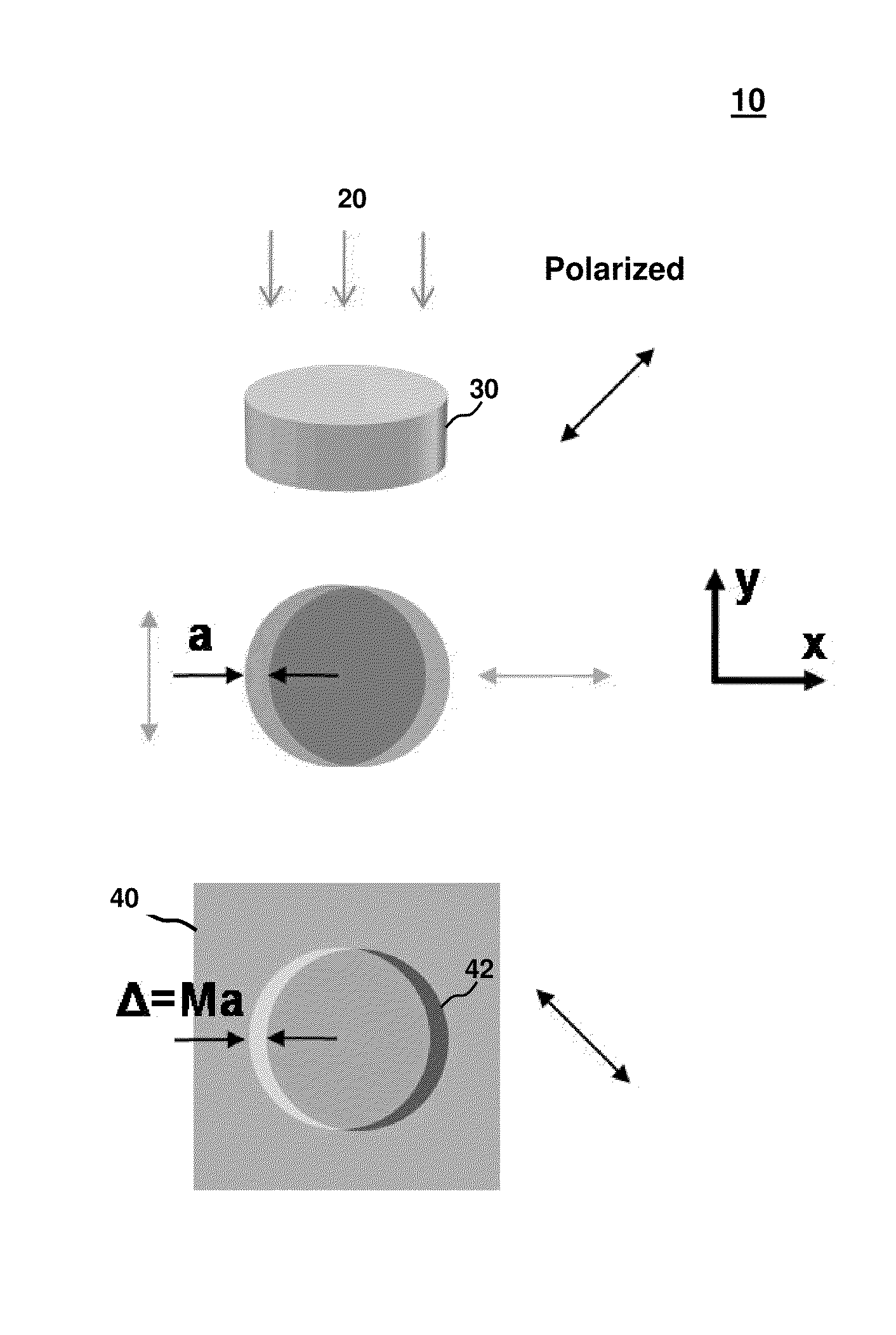
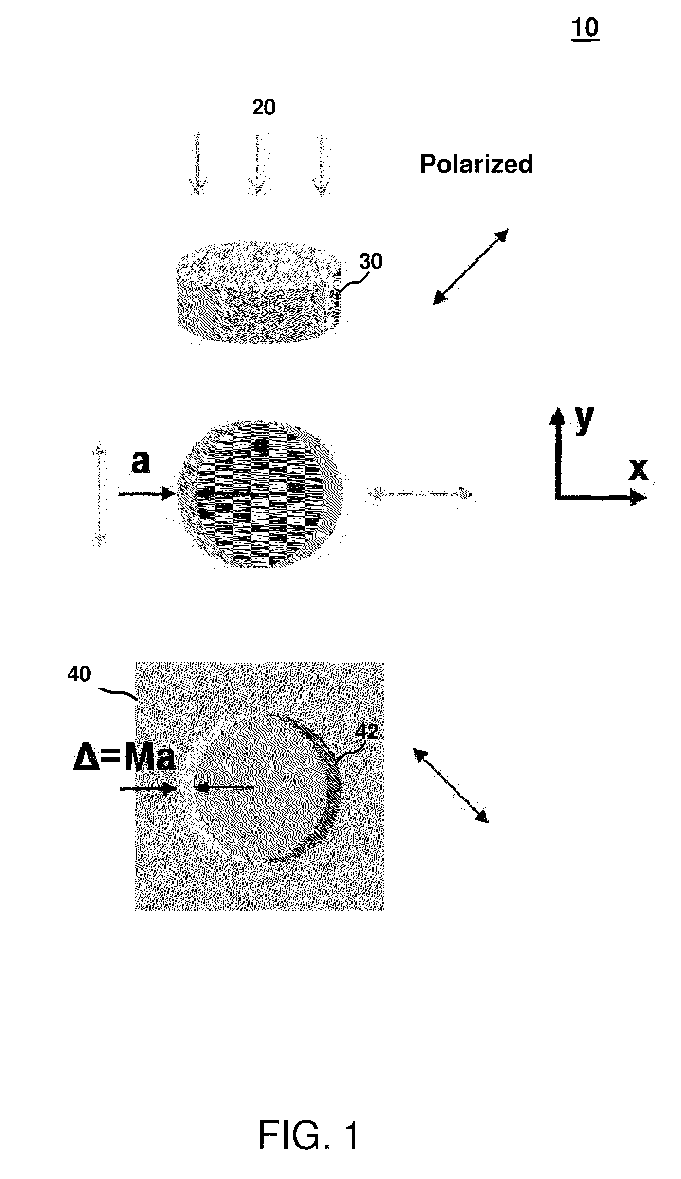
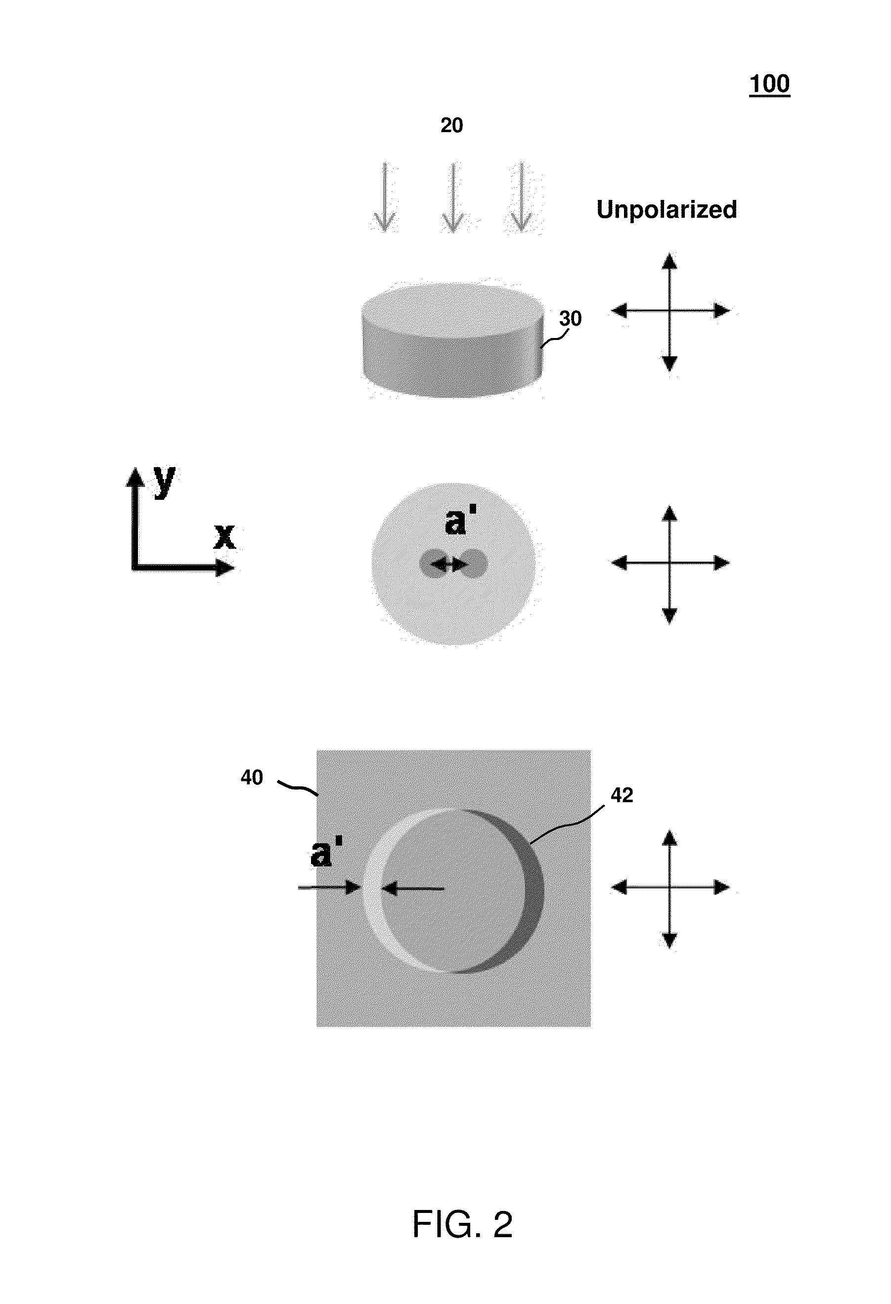
[0054]Embodiments of the present invention will be described below with reference to the accompanying drawings. Some embodiments include a simple and quantitative DIC device with a wavefront sensor that can be used in applications such as microscopy, photography, or other imaging applications.

[0055]Wavefront sensors of embodiments of the invention can be in any suitable form. For example, the wavefront sensor can be in the form of a single pixel (element) wavefront sensor. In another example, the wavefront sensor can be in the form of a one dimensional wavefront sensor array having sensor elements (e.g., pixels) located along a single direction. In another example, the wavefront sensor can be in the form of a two-dimensional wavefront sensor array comprising sensor elements located along two orthogonal directions.

[0056]In general, quantitative DIC devices of embodiments of the invention provide advantages because they can separately measure the amplitude and phase gradient of an ima...


PUM


Abstract

Embodiments of the present invention relate to a method for computing depth sectioning of an object using a quantitative differential interference contrast device having a wavefront sensor with one or more structured apertures, a light detector and a transparent layer between the structured apertures and the light detector. The method comprises receiving light, by the light detector, through the one or more structured apertures. The method also measures the amplitude of an image wavefront, and measures the phase gradient in two orthogonal directions of the image wavefront based on the light. The method can then reconstruct the image wavefront using the amplitude and phase gradient. The method can then propagate the reconstructed wavefront to a first plane intersecting an object at a first depth. In one embodiment, the method propagates the reconstructed wavefront to additional planes and generates a three-dimensional image based on the propagated wavefronts.

Description

CROSS-REFERENCES TO RELATED APPLICATIONS[0001]This is a non-provisional application that claims benefit of the filing date of U.S. Provisional Patent Application No. 61 / 205,487 entitled “Quantitative differential interference contrast (DIC) microscopy and its computed depth sectioning ability” filed on Jan. 21, 2009. That provisional application is hereby incorporated by reference in its entirety for all purposes.[0002]This non-provisional application is related to the following co-pending and commonly-assigned patent applications, which are hereby incorporated by reference in their entirety for all purposes:[0003]U.S. patent application Ser. No. 11 / 125,718 entitled “Optofluidic Microscope Device” filed on May 9, 2005.[0004]U.S. patent application Ser. No. 11 / 686,095 entitled “Optofluidic Microscope Device” filed on Mar. 14, 2007.[0005]U.S. patent application Ser. No. 11 / 743,581 entitled “On-chip Microscope / Beam Profiler based on Differential Interference Contrast and / or Surface Pla...

Claims


Application Information

Patent Timeline
Patent Type & Authority Applications(United States)
IPC IPC(8): G06K9/62
CPCG01B11/2441G01N21/45G02B21/367G02B21/14G02B21/18G02B21/0092
Inventor CUI, XIQUANYANG, CHANGHUEI
Owner CALIFORNIA INST OF TECH
Why Eureka
Try Eureka