
Cutting Tool Having a Retractable Nozzle

Active Publication Date: 2010-08-05
ISCAR LTD
View PDF30 Cites 31 Cited by
  • Summary
  • Abstract
  • Description
  • Claims
  • Application Information

AI Technical Summary

Benefits of technology

[0011]In the second, retracted position—the nozzle is at least partially accommodated in the fluid passage of the member body, i.e., at least a portion of the nozzle that extends outwardly from the member body in the first position is accommodated in the fluid passage in the second position. The second position can be assumed, for example, when the cutting tool is at rest, and no coolant fluid flows through the coolant conveying member. In the second position, for example, no portion of the nozzle extends over the clamping component, e.g., in order to allow appropriate access thereto. The retracted nozzle thereby allows one to comfortably index or replace the cutting insert, e.g., without having to dismount or completely remove the coolant conveying member from the cutting tool, and without having to provide the cutting insert with inappropriate securing.

Problems solved by technology

During performance of intensive metal cutting operations, for example, during turning of hard metals, a cutting insert performing the operation accumulates excessive amounts of heat, due to the continuous interaction with the machined work-piece.
Without means for expelling the excessive heat, the cutting insert gradually risks, for example, deforming and eventually damaging the work-piece.
However, by extending over the cutting insert, the nozzle blocks access to a clamping component that secures the cutting insert in place, and impedes the releasing of the clamping component, thus complicating the indexing or replacing of the cutting insert.
However, these clamping arrangements provide the cutting insert with inappropriate securing, and may be inadequate, for example, for intensive cutting operations, which require significantly solid securing of the cutting insert.

Method used


Image

  • Cutting Tool Having a Retractable Nozzle
  • Cutting Tool Having a Retractable Nozzle
  • Cutting Tool Having a Retractable Nozzle

Examples


Embodiment Construction

[0025]In the following description, various aspects of the present invention will be described. For purposes of explanation, specific configurations and details are set forth in order to provide a thorough understanding of the present invention. However, it will also be apparent to one skilled in the art that the present invention may be practiced without the specific details presented herein. Furthermore, well-known features may be omitted or simplified in order not to obscure the present invention.

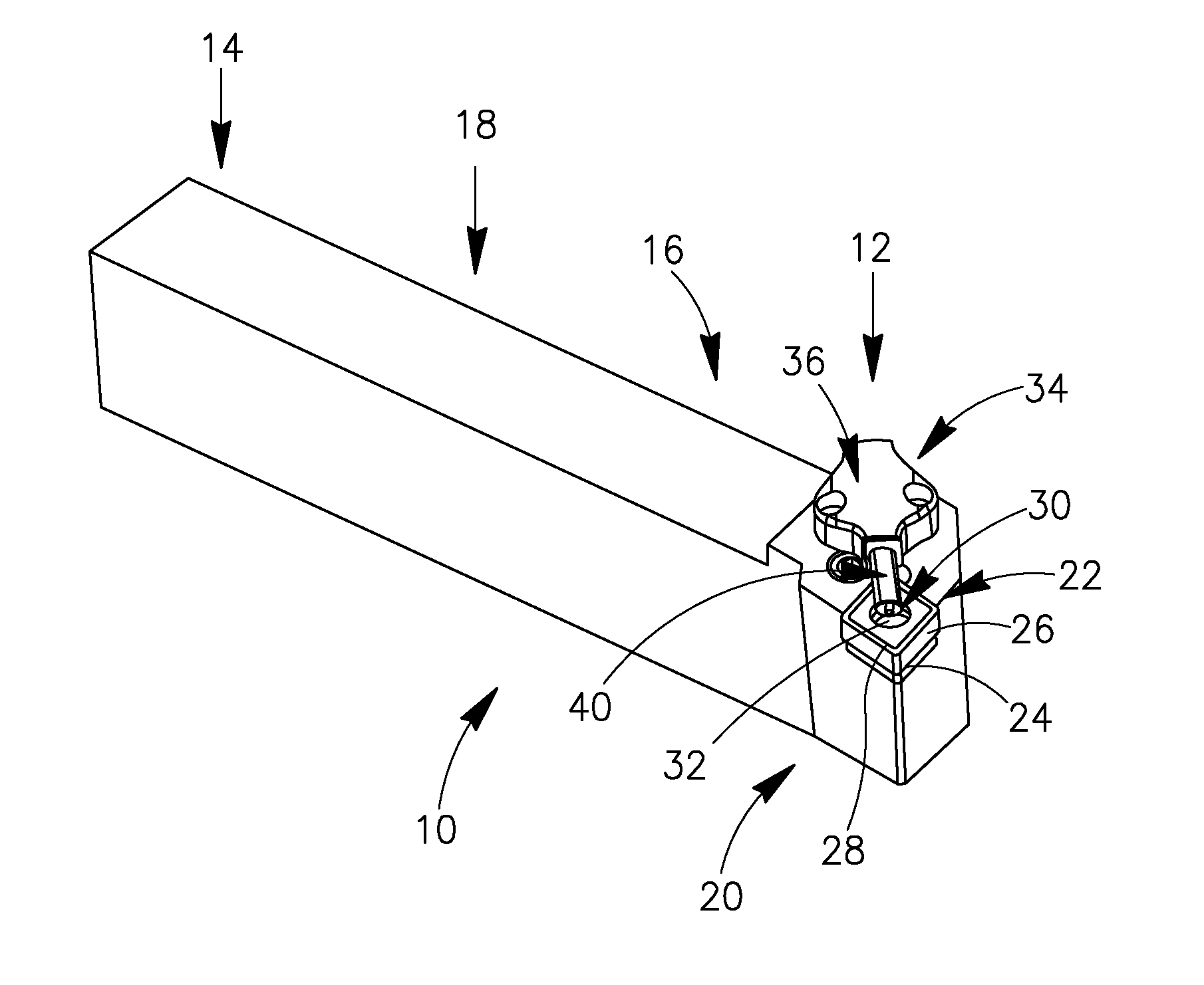
[0026]Although some drawings herein show a turning tool, the present invention is not limited in this respect. For example, embodiments of the invention may refer to other cutting tools, e.g., to grooving tools, parting tools, or to other metal cutting tools having one or more cutting inserts releasably retained therein.

[0027]Additionally, although some drawings herein show a cutting insert having a generally rhombic shape, the present invention is not limited in this respect. For exampl...


PUM

PropertyMeasurementUnit
Flow rateaaaaaaaaaa

Abstract

A cutting tool includes a coolant conveying member, to provide coolant fluid to a cutting area during a cutting operation. The coolant conveying member includes a member body having a fluid passage formed therein, and a nozzle to convey and to jet out the coolant fluid therethrough. The nozzle is shiftable relative to the member body, between a first, extended position and a second, retracted position. In the extended position, for example, assumed during the cutting operation—the nozzle extends out and forwardly from the member body, stabilized by the continuous flow of coolant fluid therethrough, forcing the nozzle forwardly. In the retracted position, for example, assumed when the when the coolant fluid does not flow through the coolant conveying member, or flows at a very low rate, the nozzle may be at least partially accommodated in the fluid passage, to allow, for example, indexing or replacing of the cutting insert.

Description

FIELD OF THE INVENTION[0001]The present invention relates to a cutting tool having a coolant conveying member to convey coolant fluid to a cutting area, the coolant conveying member having a retractable nozzle.BACKGROUND OF THE INVENTION[0002]During performance of intensive metal cutting operations, for example, during turning of hard metals, a cutting insert performing the operation accumulates excessive amounts of heat, due to the continuous interaction with the machined work-piece. Without means for expelling the excessive heat, the cutting insert gradually risks, for example, deforming and eventually damaging the work-piece.[0003]A well known solution to the above problem includes providing a continuous flow of coolant fluid to the cutting area, during the cutting operation. The coolant fluid can be supplied to the cutting area, for example, using a coolant conveying member—which may either be formed integrally in the body of the cutting tool, or include a separate unit which is...

Claims


Application Information

Patent Timeline
IPC IPC(8): B23Q11/10B23B29/12
CPCB23B27/10B23Q11/10Y10T408/46Y10T407/14Y10T408/44Y10T407/2272B23Q11/1084B23B27/16B23B2231/24
Inventor AMSTIBOVITSKY, LEONIDNEIMAN, GRIGORI
Owner ISCAR LTD
Features
  • Generate Ideas
  • Intellectual Property
  • Life Sciences
  • Materials
  • Tech Scout
  • Unparalleled Data Quality
  • Higher Quality Content
  • 60% Fewer Hallucinations
Learn More