Closed-loop control for a gas turbine with actively stabilized compressor

Inactive Publication Date: 2010-08-05
MTU AERO ENGINES GMBH
View PDF9 Cites 16 Cited by
  • Summary
  • Abstract
  • Description
  • Claims
  • Application Information

AI Technical Summary

Benefits of technology

[0055]Another advantage of the invention is that it does not require additional expensive and sensitive instrumentation, which would have a negative effect on reliability, manufacturing costs and maintenance costs. Essentially the existing instrumentation for engine operation is used.
[0056]In addition, the present invention may also be combined with measurement technology for pressure and clearances and would therefore supply the redundancy required for a sensitive measurement technology. The operational reliability of engines would be increased accordingly and a smaller safety margin would be required in the design of the stability limit of the compressor.
[0057]Furthermore, the inventive approach is suitable for inexpensive retrofitting of existing engines.
[0058]Engines in the development

Problems solved by technology

A stall in the compressor components of the engine leads to engine pumping and may result in loss of the aircraft.
Thus, based on physical principles derived from the operating performance of the overall engine system, but also for reasons of reliability of such a highly sensitive pressure measurement designed for detection of high frequencies, such an approach will not be successful in all operating cases.
This causes higher turbine temperatures and higher operating points in the characteristics map of the compressor and thus a smaller stability interval.
Due to the great difference in time constants in the thermal expansion of the casing and rotating components, this temporarily results in very great radial clearances between the rotating blades and the casing.
Both variants rely on sensitive sensor systems, which in many cases are inadequate to meet the demands of rough engine operation and can lead to increased maintenance costs and production disturbances.
However, these intervention measures are performed only in response to an instability in the engine that has a

Method used


Image

  • Closed-loop control for a gas turbine with actively stabilized compressor
  • Closed-loop control for a gas turbine with actively stabilized compressor
  • Closed-loop control for a gas turbine with actively stabilized compressor

Examples


Example

DETAILED DESCRIPTION OF THE DRAWINGS

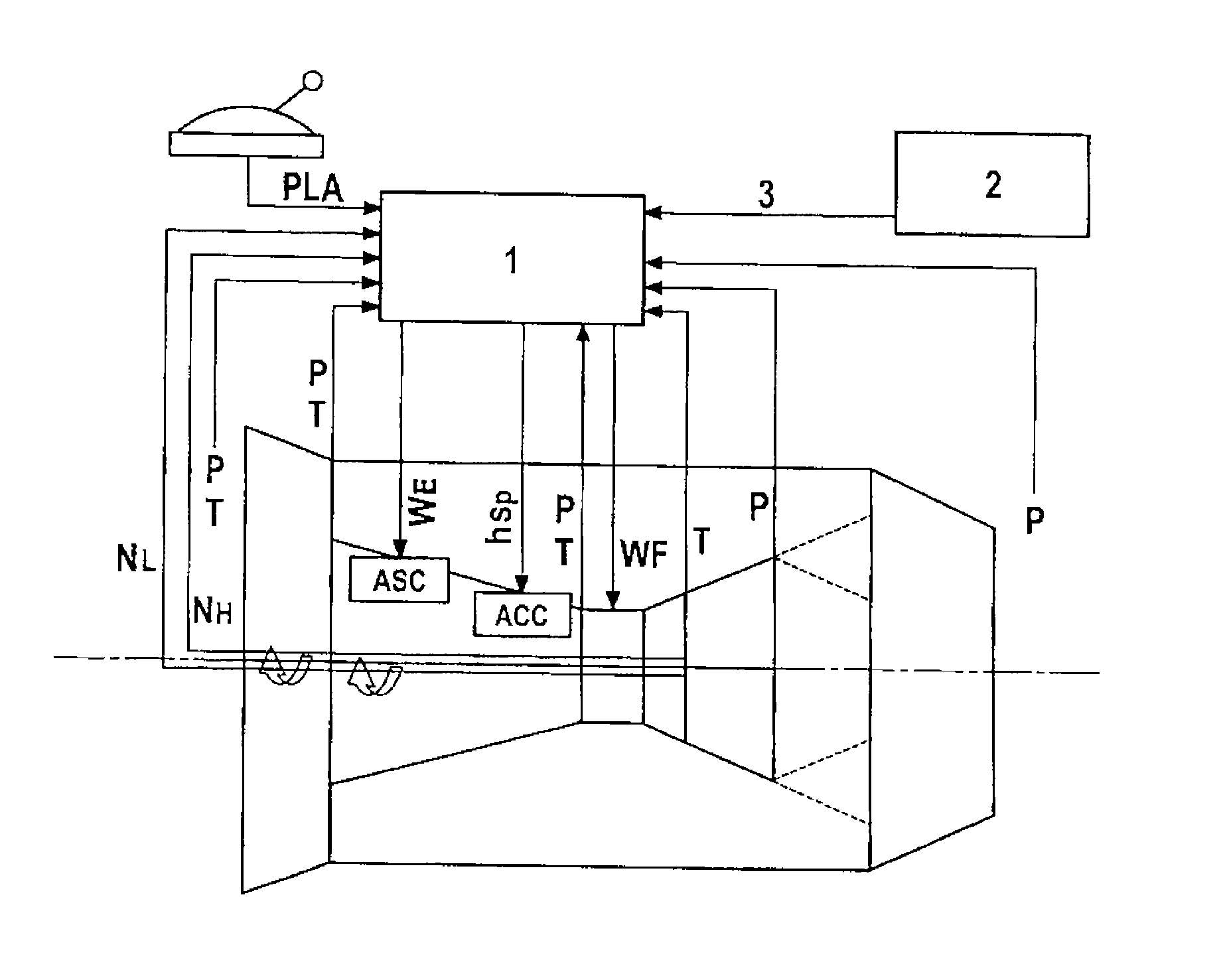
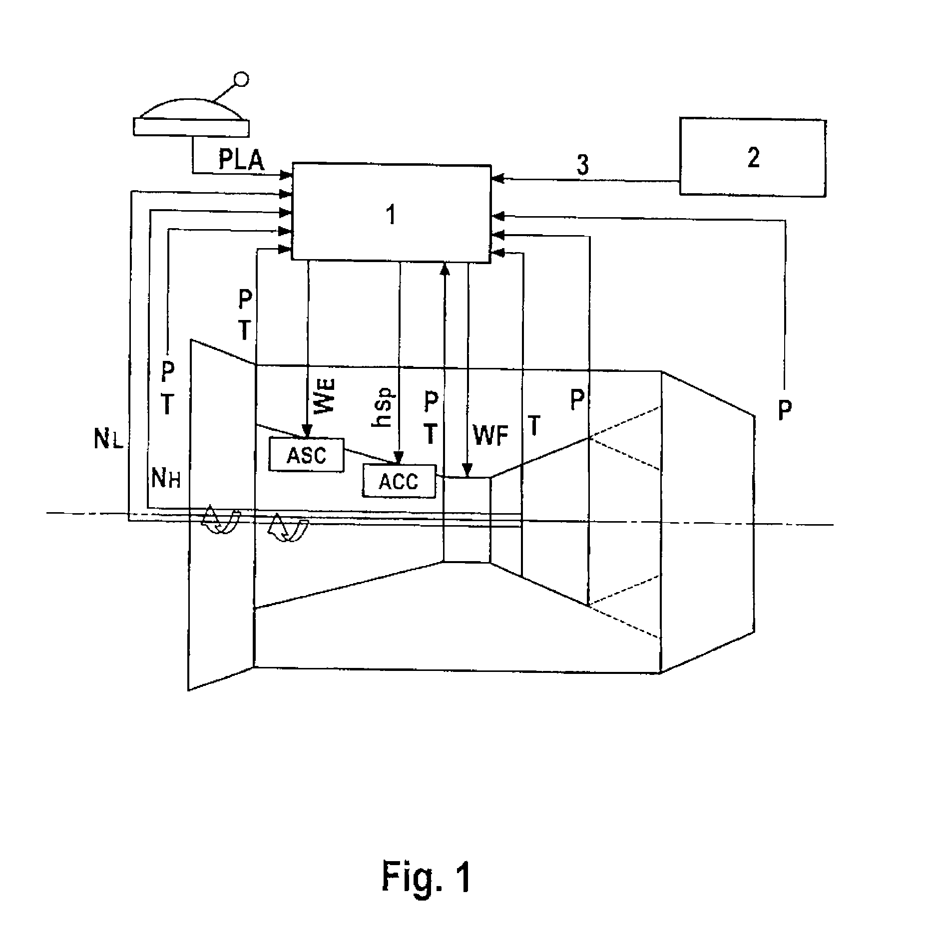
[0067]FIG. 1 shows a schematic diagram of an inventive regulating system for a gas turbine having an actively stabilized compressor. This shows that the engine data detected for the general engine control, such as temperatures T, pressures P, rotational speed measurements NL, NH and thrust lever setting PLA also form the input parameters for the engine regulator 1 of the inventive regulating system. In addition, data from aircraft avionics 2 indicating the flight position and flight maneuver 3 may also be used. Using these parameters already detected in the prior art, the algorithms stored in the inventive regulating system, the clearance model and the anticipation logic are acted upon. The corresponding devices on the compressor are controlled through appropriate control signals WE for the blade-tip injection ASC (active surge control) and hsp for clearance control ACC (active clearance control). Control of fuel injection WF should be mentioned o...


PUM


Abstract

A regulating system for a gas turbine, in particular an aircraft engine, has devices for blade-tip injection for increasing the compressor stability, these devices being activated as needed. The regulating system has devices for active clearance control, preferably in the high-pressure compressor, with which the radial clearance in the high-pressure compressor is kept in an optimum operating range, and the regulating system has a shared engine regulator for both devices. The technical problems of the prior art are avoided through the present invention, and an improved regulating system for a gas turbine, in particular an aircraft engine, is made available for active stabilization of the compressor.

Description

[0001]This application claims the priority of International Application No. PCT / DE2008 / 001176, filed Jul. 17, 2008, and German Patent Document No. 10 2007 035 927.8, filed Jul. 31, 2007, the disclosures of which are expressly incorporated by reference herein.BACKGROUND AND SUMMARY OF THE INVENTION[0002]The invention relates to a regulating system for a gas turbine, in particular an aircraft engine, such that the regulating system has devices for blade-tip injection (ASC, active surge control) to increase compressor stability and devices for active clearance control (ACC), preferably in the high-pressure compressor. Furthermore, the invention relates to a method for regulation of a gas turbine, in particular an aircraft engine.[0003]The reserve stability of compressors in gas turbine engines is crucial for safe operation of the engine. A stall in the compressor components of the engine leads to engine pumping and may result in loss of the aircraft. Such an event must therefore be pre...

Claims


Application Information

Patent Timeline
IPC IPC(8): F02C9/18F01D11/20
CPCF01D11/24F02C9/18F04D27/0207F05D2270/1022F05D2270/102F05D2270/101Y02T50/671F04D27/0238F04D27/0246F04D29/164Y02T50/60
Inventor HORN, WOLFGANGSCHMIDT, KLAUS-JUERGEN
Owner MTU AERO ENGINES GMBH
Why Eureka
Try Eureka