Method and apparatus for introducing auxiliary material

a technology of auxiliary materials and flow paths, applied in liquid degasification, separation processes, instruments, etc., can solve the problem that auxiliary materials introduced into the flow path of crude gas streams will pass counter to the normal flow direction into the application region, and achieve the effect of avoiding the flow path of auxiliary materials into the application region

Active Publication Date: 2010-08-05
DUERR SYST AG
View PDF11 Cites 19 Cited by
  • Summary
  • Abstract
  • Description
  • Claims
  • Application Information

AI Technical Summary

Benefits of technology

[0007]The underlying object of the present invention is to provide a method of the initially described type, with which an introd...

Problems solved by technology

If there is not such an adequate crude gas flow through the at least one filter element, there is the risk that auxiliary material intro...

Method used


Image

  • Method and apparatus for introducing auxiliary material
  • Method and apparatus for introducing auxiliary material
  • Method and apparatus for introducing auxiliary material

Examples


Embodiment Construction

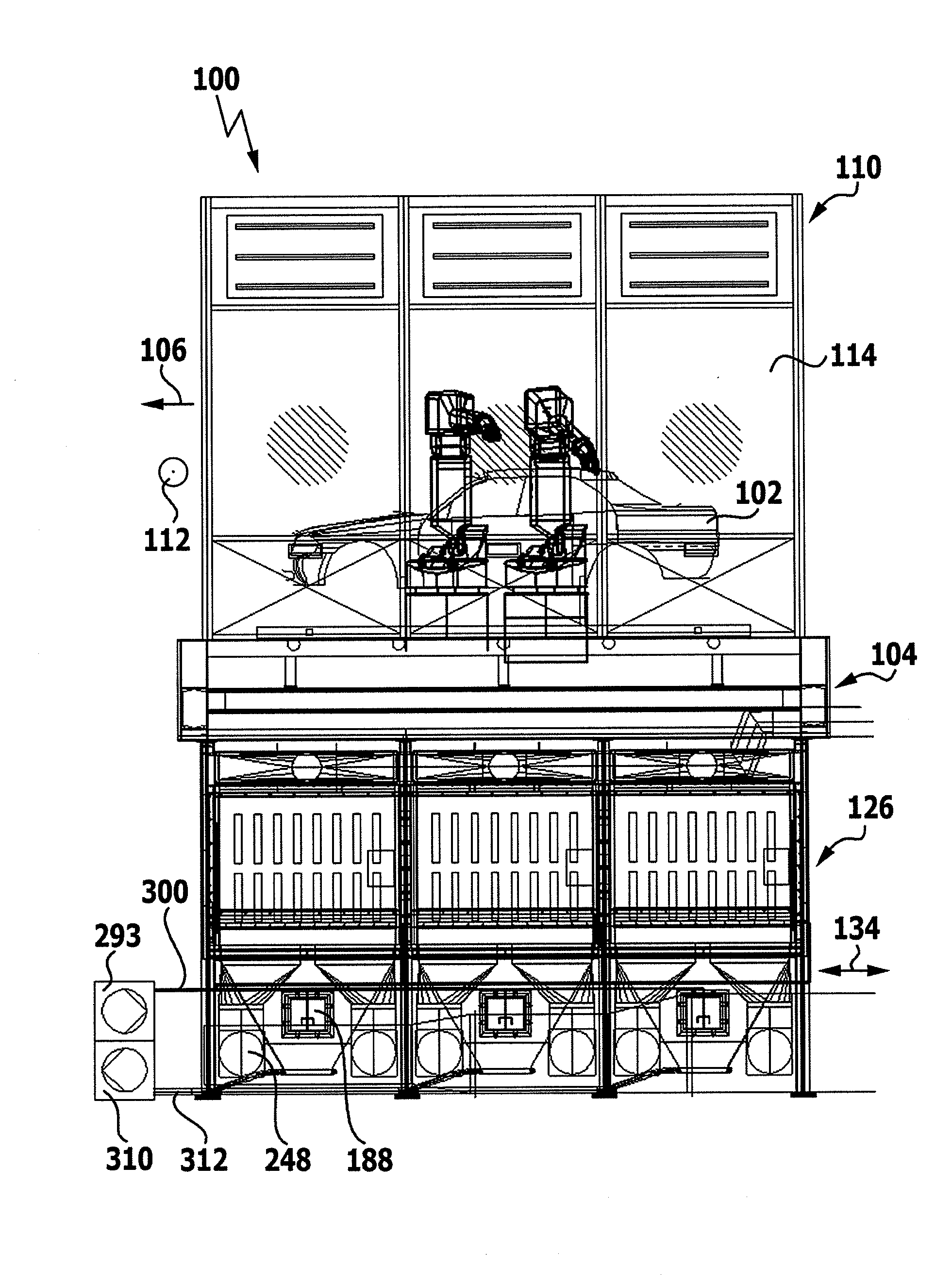
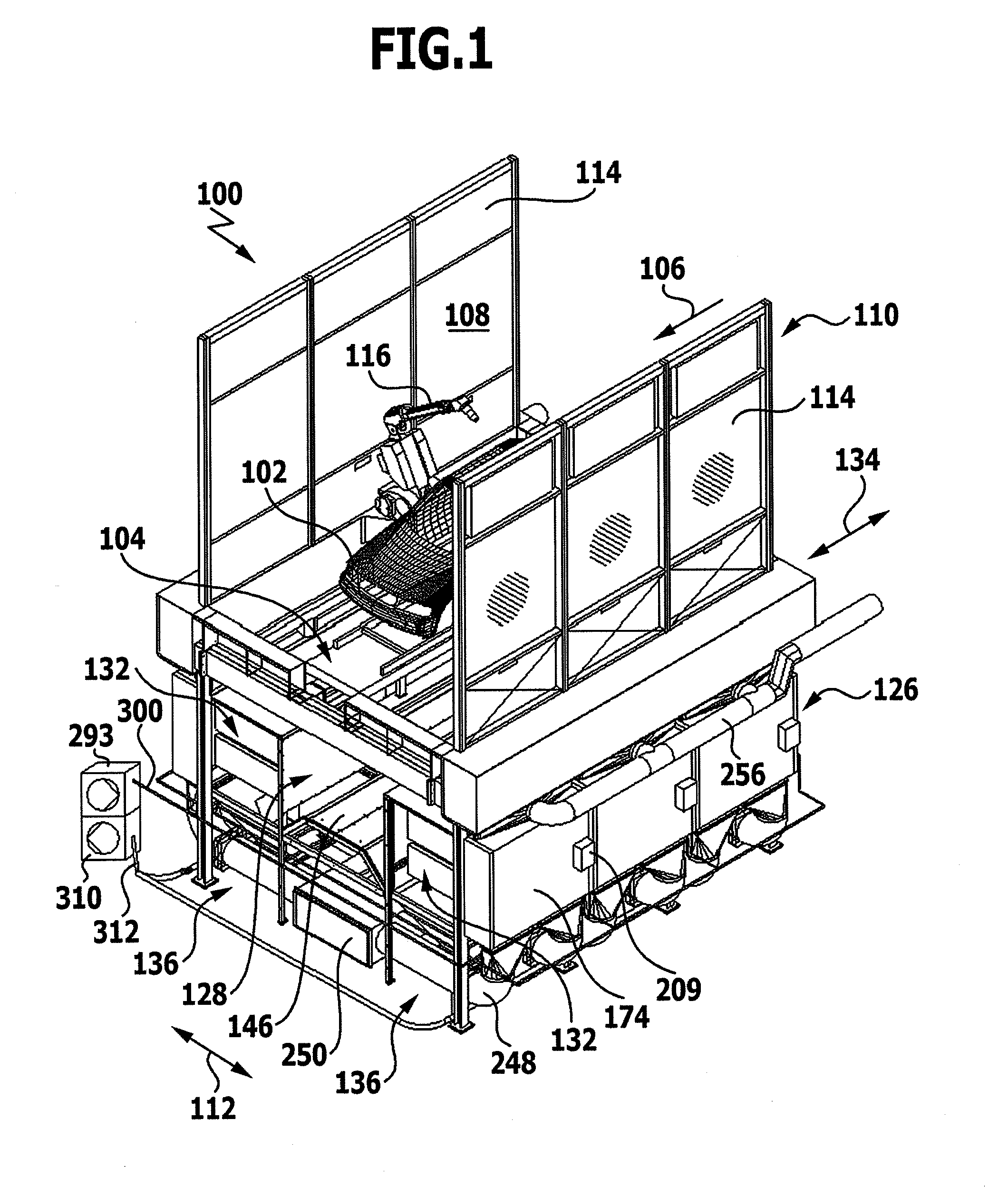
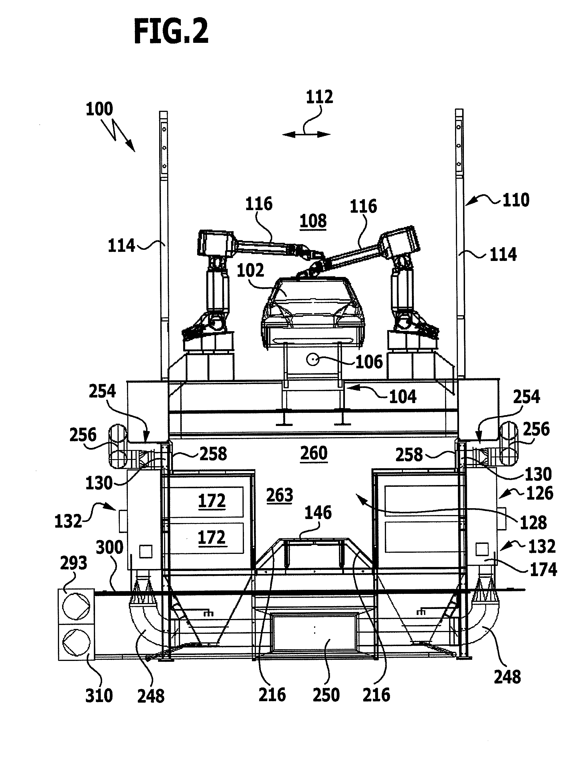
[0059]An installation for spray-painting vehicle bodies 102, which is illustrated in FIGS. 1 to 19 and denoted as a whole by 100, comprises a purely diagrammatically illustrated conveying apparatus 104, by means of which the vehicle bodies 102 may be moved along a conveying direction 106 through an application region 108 of a spray booth denoted as a whole by 110.

[0060]The application region 108 is the interior of the spray booth 110, which in a horizontal transverse direction 112 extending at right angles to the conveying direction 106, which corresponds to the longitudinal direction of the spray booth 110, is delimited on either side of the conveying apparatus 104 by a booth wall 114.

[0061]In the spray booth 110 spray-painting devices 116, for example in the form of painting robots, are disposed on both sides of the conveying apparatus 104.

[0062]By means of a recirculation air circuit (illustrated only in sections) an air stream is generated, which passes through the application r...


PUM

PropertyMeasurementUnit
Flow rateaaaaaaaaaa
Pressure dropaaaaaaaaaa

Abstract

In order to provide a method of introducing auxiliary material into the flow path of a crude gas stream charged with wet-paint overspray before the crude gas stream passes through at least one filter element for separating the overspray from the crude gas stream, with which method an introduction of auxiliary material into the application region of a paint shop is reliably prevented even in the event of incorrect operation, a method is proposed, which comprises the following method steps: detecting whether there is an adequate crude gas flow through the at least one filter element; and blocking the introduction of auxiliary material into the flow path of the crude gas stream if it is determined that there is not an adequate crude gas flow.

Description

RELATED APPLICATION[0001]This application is a continuation application of PCT / EP2008 / 005482 filed Jul. 4, 2008, the entire specification of which is incorporated herein by reference.FIELD OF THE DISCLOSURE[0002]The present invention relates to a method of introducing auxiliary material into the flow path of a crude gas stream charged with wet-paint overspray before the crude gas stream passes through at least one filter element for separating the overspray from the crude gas stream.BACKGROUND[0003]Such a method is known for example from DE 10 2005 048 579 A1.[0004]With this known apparatus the dry separation of the wet-paint overspray from the crude gas stream of a spray booth is effected in a filtering apparatus after a flowable, particulate auxiliary material, known as a “precoat” material, has previously been delivered into the crude gas stream by means of a nozzle arrangement.[0005]The purpose of this auxiliary material is to deposit as a barrier layer on the surfaces of the fi...

Claims


Application Information

Patent Timeline
IPC IPC(8): B05B15/12B01D46/46B01D19/00B05B14/43
CPCB01D46/0035B01D46/0041B01D46/42B05B13/0452B05B15/1255G01F23/263B01D46/46B01D2273/12B05B14/437Y02P70/10B01D46/00
Inventor HOLZHEIMER, JENSWIELAND, DIETMAR
Owner DUERR SYST AG
Why Eureka
Try Eureka