
Stable approach monitor (SAM) system

a monitor and monitor technology, applied in the field of stable approach monitor, can solve the problems of needing post-flight inspection of the flap system, structural damage to the flap, and excessive aircraft speed, and achieve the effect of reducing the speed of the aircraft and more accurate audible alerts

Active Publication Date: 2010-08-05
HONEYWELL INT INC
View PDF31 Cites 3 Cited by
  • Summary
  • Abstract
  • Description
  • Claims
  • Application Information

AI Technical Summary

Benefits of technology

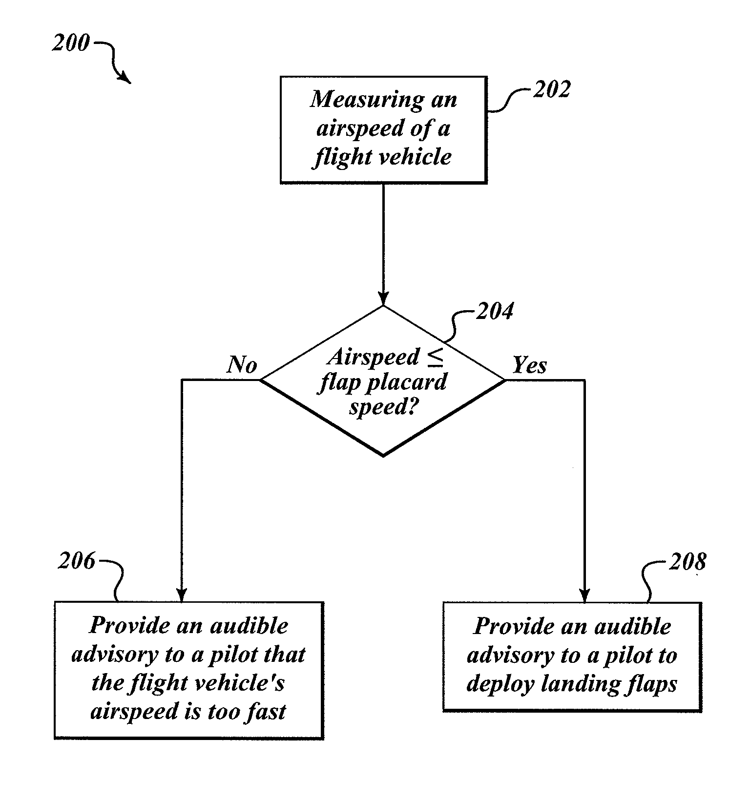
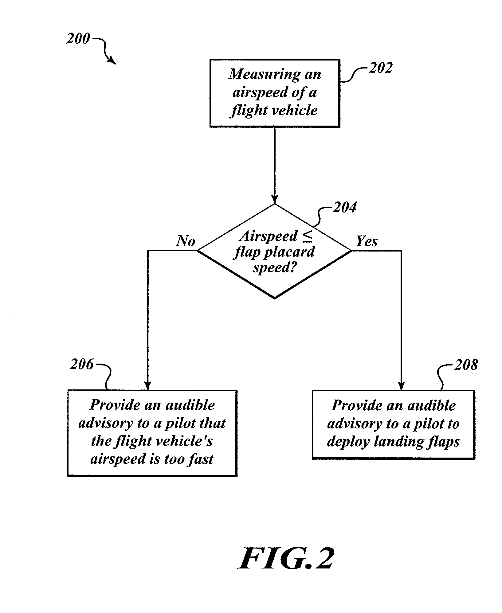
[0004]The present invention generally relates to an improvement for a Stable Approach Monitor (SAM) system to provide more accurate audible advisories to a pilot when an aircraft is on its final landing approach. More specifically, the improved SAM system compares a measured airspeed of the aircraft to a predetermined flap placard speed. If the measured airspeed exceeds the predetermined flap placard speed then the improved SAM system provides an audible advisory indicating the speed of the aircraft is too fast (e.g., “TOO FAST, TOO FAST”). Advantageously, such an audible advisory should prevent the pilot from attempting to deploy the flaps at an excessive aircraft speed, and in turn should focus the pilot's attention on the problem at hand, which would be to reduce the speed of the aircraft before making any attempt to deploy the flaps. Once the speed of the aircraft is equal to or below the predetermined flap placard speed, the improved SAM system may then provide an audible advisory informing the pilot to deploy the flaps (e.g., “FLAPS-FLAPS”).

Problems solved by technology

One drawback of the existing SAM is when the aircraft speed is too high on final approach for landing flaps to have not been set.
If the pilot were to heed the advisory and deploy the flaps, there is a potential for structural damage to the flaps and the potential that a post-flight inspection of the flap system will be required.

Method used


Image

  • Stable approach monitor (SAM) system
  • Stable approach monitor (SAM) system
  • Stable approach monitor (SAM) system

Examples


Embodiment Construction

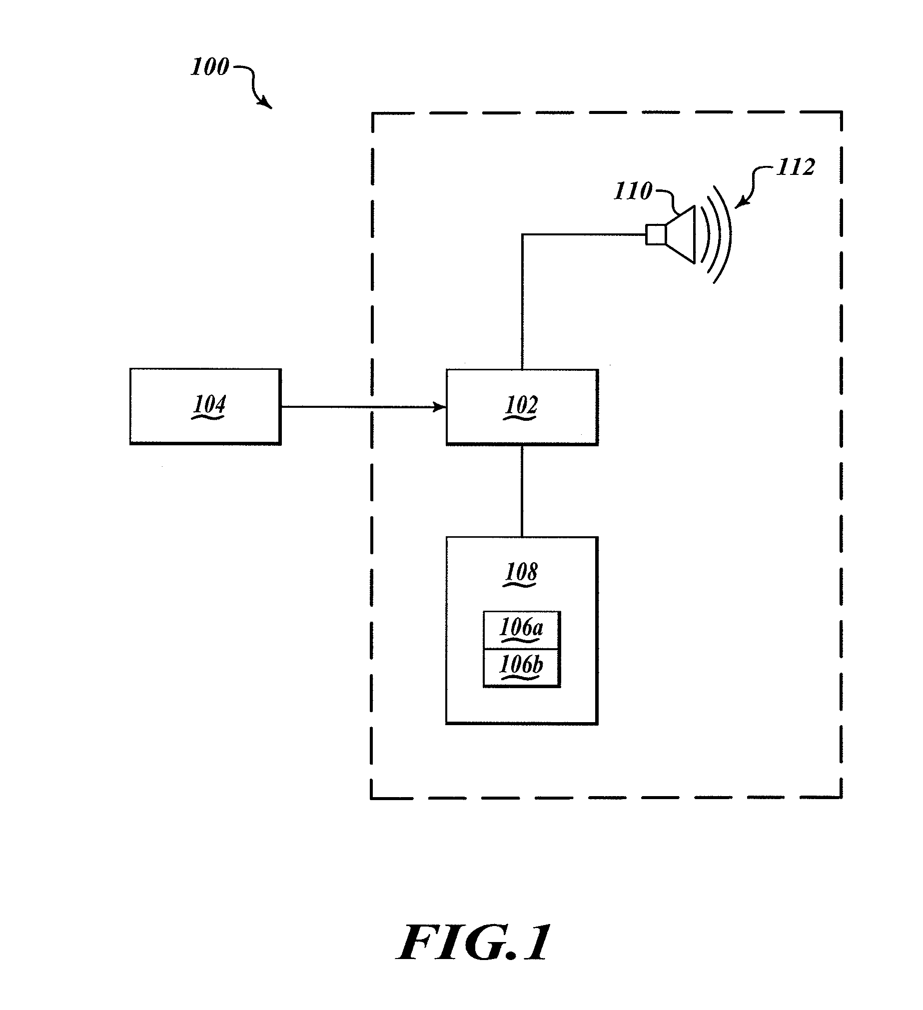
[0010]FIG. 1 shows an improved Stable Approach Monitor (SAM) system 100 having a controller or processor 102 that receives a measured airspeed 104 of an aircraft (not shown) from an airspeed measurement device 104, which may take the form of a pressure sensor. The processor 102 operates to compare the measured airspeed 104 to a predetermined flap placard speed 106a and to a set of stability criteria 106b. The predetermined flap placard speed 106a, the set of stability criteria 106b and other parameters may be stored in a memory 108 accessibly by the processor 102.

[0011]The predetermined flap placard speed 106a corresponds to a flap deployment speed determined by a structural capacity of the aircraft's flap system. The structural capacity relates to the structural design airspeeds as a function of altitude. In some cases, the structural design airspeeds are dictated or at least defined by government regulations. The predetermined flap placard speed 106a is a function of flap position...


PUM


Abstract

An improved stable approach monitor (SAM) system provides an audible advisory to a pilot when an aircraft is on a final landing approach. More specifically, the SAM system compares a measured airspeed of the aircraft to a predetermined flap placard speed. If the measured airspeed exceeds the predetermined flap placard speed then the improved SAM system provides an audible advisory indicating the airspeed of the aircraft is too fast. Advantageously, this audible advisory should prevent the pilot from attempting to deploy the flaps at an excessive airspeed and in turn focuses the pilot's attention on the problem at hand, which would be to reduce the airspeed of the aircraft. Once the airspeed is equal to or below the predetermined flap placard speed, the improved SAM system may provide another audible advisory informing the pilot to commence deployment of the flaps.

Description

BACKGROUND OF THE INVENTION[0001]A conventional Stable Approach Monitor (SAM) operates to reduce landing risks and runway excursions by providing one or more audible advisories developed around a set of stable approach criteria. Generally, the stable approach criteria are developed around the Standard Operating Procedure (SOP) used by most major airlines and criteria developed by the Flight Safety Foundation. By way of example, the stable approach criteria may include altitude gates (i.e., height above runway) in which the “stability” of the aircraft is determined. In addition, the stable approach criteria provides that at these altitude gates, the aircraft must be properly configured to land, for example flaps at least partially deployed and the landing gear down. The aircraft must be on a proper glide slope and be traveling at or near a predetermined speed. In one sense, the stable approach criteria may determine a “stability envelope” such that if the aircraft is outside that env...

Claims


Application Information

Patent Timeline
Patent Type & Authority Applications(United States)
IPC IPC(8): G05D1/00
CPCG01C23/005G08G5/025G05D1/0676
Inventor ISHIHARA, YASUOCONNER, KEVIN J.JOHNSON, STEVE
Owner HONEYWELL INT INC
Learn More