
Gas insulated transmission line having improved performance of electric contact at connection parts of the conductors

a technology of electric contact and transmission line, which is applied in the direction of electric cable installation, line/current collector details, and gas/oil presence, can solve the problems of gas insulated transmission line maintenance cost, reduce transmission capacity, and reduce allowable current, so as to reduce the amount of generated heat and prevent the reduction of allowable current of the transmission line

Inactive Publication Date: 2010-08-12
DONGBU HITEK CO LTD +1
View PDF4 Cites 12 Cited by
  • Summary
  • Abstract
  • Description
  • Claims
  • Application Information

AI Technical Summary

Benefits of technology

[0018]Disclosed herein is a gas insulated transmission line having improved electric contact performance and maximized allowable current by increasing an electric contact area of a sliding conductor connector.
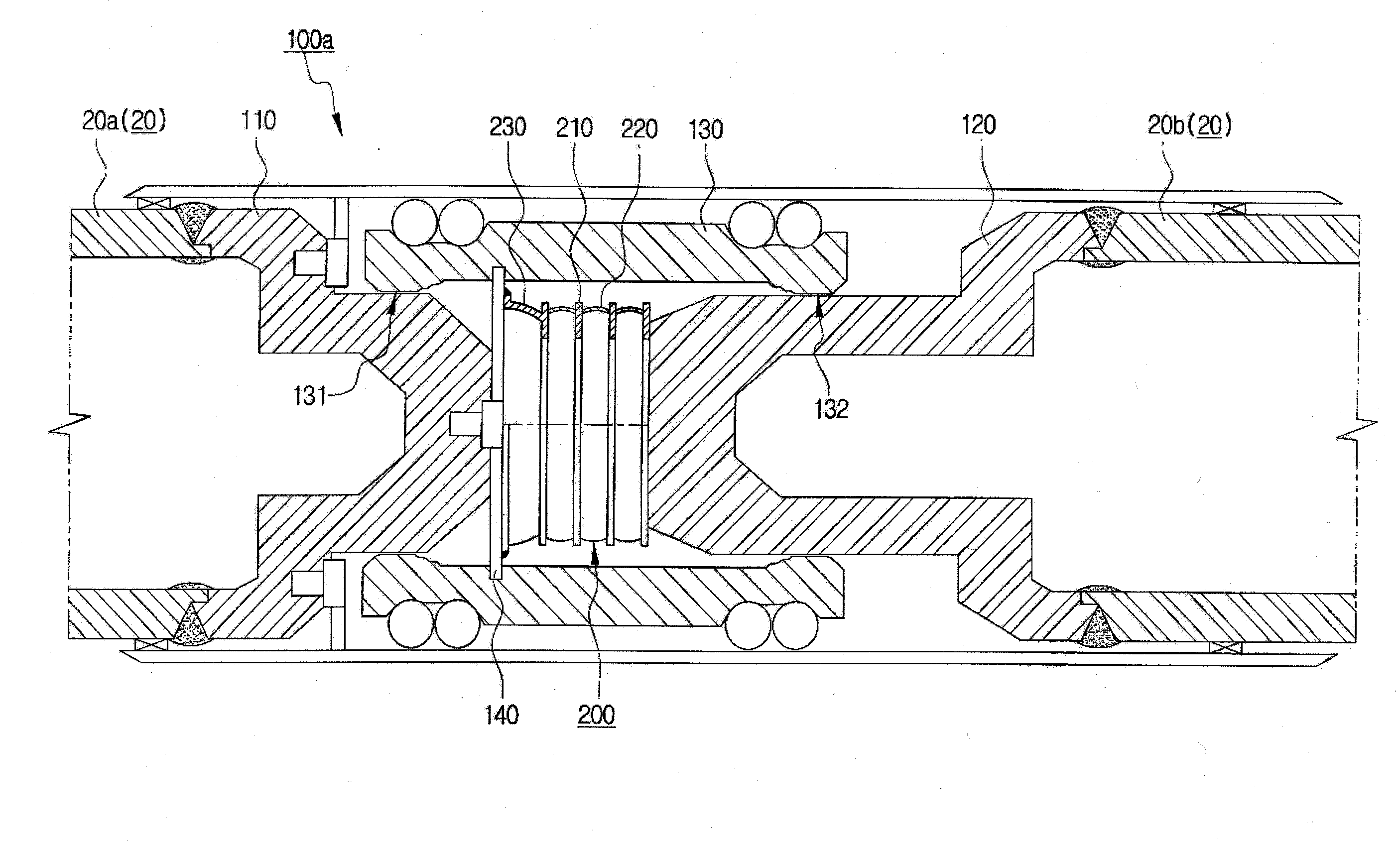
[0022]The gas insulated transmission line provides a wide axial contact area while allowing thermal expansion / shrinkage of conductors, and also the gas insulated transmission line further provides an axial contact area in addition to the radial contact achieved by the existing sliding contact manner. Thus, the gas insulated transmission line may decrease an amount of generated heat and prevent reduction of allowable current of the transmission line by increasing an electric contact area at connection ports between conductors.

Problems solved by technology

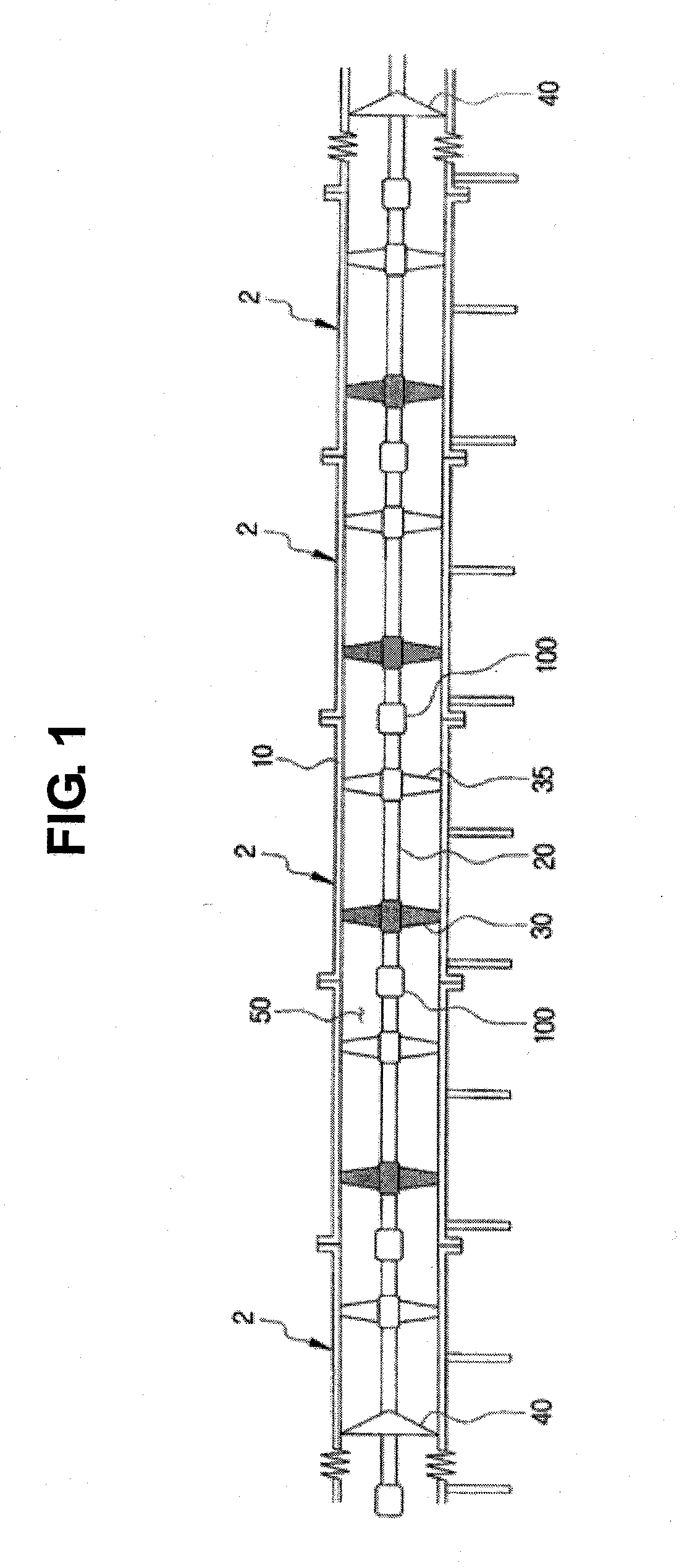
Such a gas insulated transmission line is suitable for a large capacity underground line, and once installed, the gas insulated transmission line demands small maintenance costs, since it is sufficient to check it by naked eyes only once in a few years.
Also, the gas insulated transmission line is suitable for downtown areas that do not easily allow installation of overhead transmission lines and demands underground installations of transmission lines.
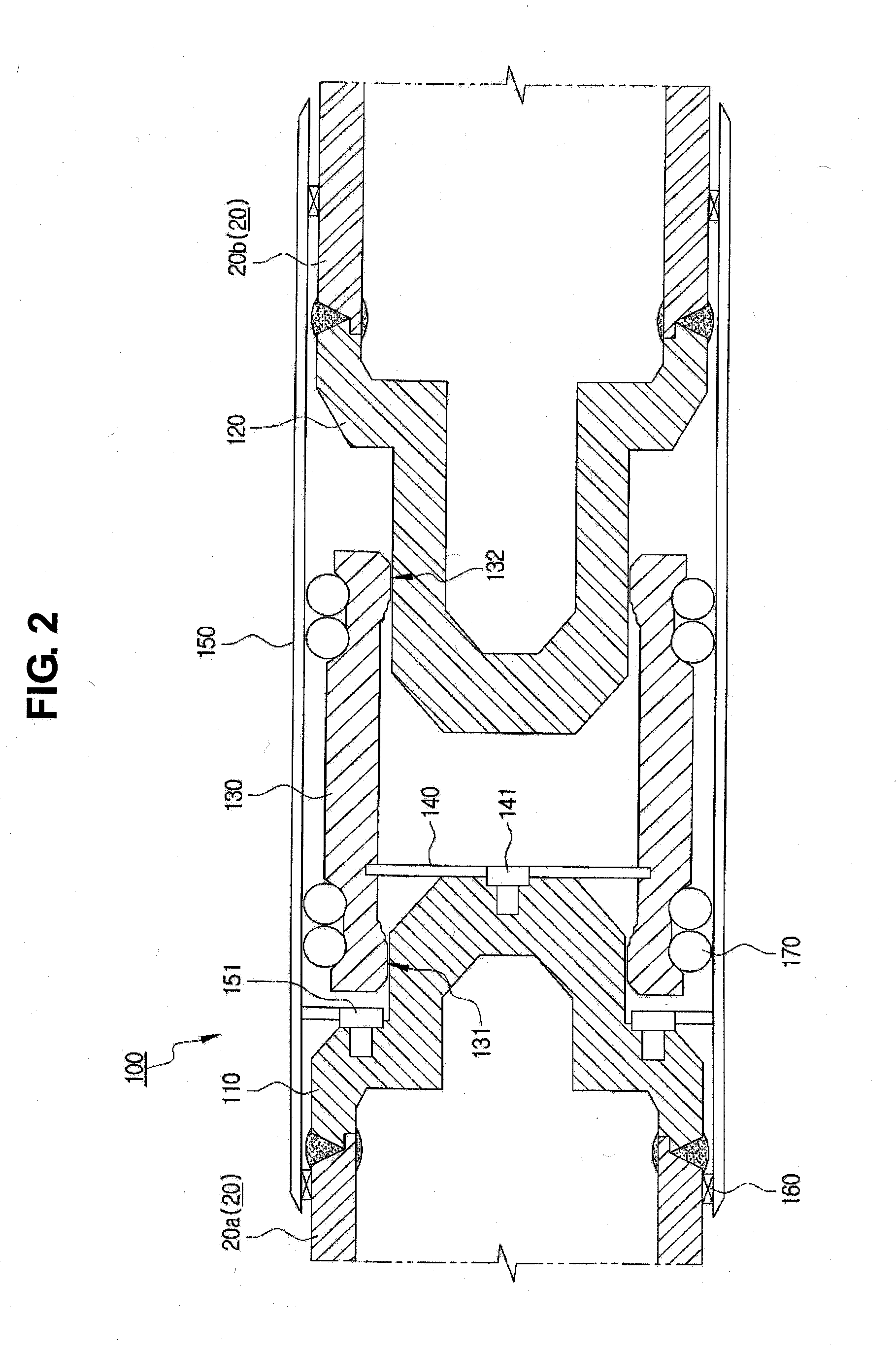
For example, if the contact area is small, an amount of heating is increased due to the increase of contact resistance, and the increased amount of heating causes reduction of allowable current (namely, reduction of transmission capacity).
As a result, the sliding conductor connector 100 does not provide a sufficient contact area, which increases an amount of heat and reduces allowable electric current, although it may easily cope with thermal expansion of conductors since the socket 120 and the connection sleeve 130 are contacted in a sliding contact manner in a radial direction.

Method used


Image

  • Gas insulated transmission line having improved performance of electric contact at connection parts of the conductors
  • Gas insulated transmission line having improved performance of electric contact at connection parts of the conductors
  • Gas insulated transmission line having improved performance of electric contact at connection parts of the conductors

Examples


Embodiment Construction

[0028]Exemplary embodiments now will be described more fully hereinafter with reference to the accompanying drawings, in which exemplary embodiments are shown. This disclosure may, however, be embodied in many different forms and should not be construed as limited to the exemplary embodiments set forth therein. Rather, these exemplary embodiments are provided so that this disclosure will be thorough and complete, and will fully convey the scope of this disclosure to those skilled in the art. In the description, details of well-known features and techniques may be omitted to avoid unnecessarily obscuring the presented embodiments.

[0029]The terminology used herein is for the purpose of describing particular embodiments only and is not intended to be limiting of this disclosure. As used herein, the singular forms “a”, “an” and “the” are intended to include the plural forms as well, unless the context clearly indicates otherwise. Furthermore, the use of the terms a, an, etc. does not de...


PUM


Abstract

The gas insulated transmission line includes: a pair of conductors disposed in a length direction; a fixed-side socket and a movable-side socket respectively coupled to one ends of the conductors; and a conductive flexible member interposed between facing end surfaces of the fixed-side socket and the movable-side socket, both ends of the conductive flexible member being closely adhered to the end surfaces of the fixed-side socket and the movable-side socket to keep electric contact therebetween, and the conductive flexible member being expanded or shrunken in an axial direction according to thermal expansion / shrinkage of the pair of conductors. The gas insulated transmission line provides a wide axial contact area while allowing thermal expansion / shrinkage of conductors.

Description

CROSS-REFERENCE TO RELATED APPLICATION[0001]This application claims priority to Korean Patent Application No. 10-2009-0010981, filed on Feb. 11, 2009, and all the benefits accruing therefrom under 35 U.S.C. §119, the contents of which in its entirety are herein incorporated by reference.BACKGROUND[0002]1. Field[0003]This disclosure relates to a gas insulated transmission line, and more particularly to a gas insulated transmission line having improved electric contact performance and maximized allowable current by increasing an electric contact area of connection parts of conductors.[0004]2. Description of the Related Art[0005]A gas insulated transmission line (GIL) or compressed gas insulated transmission line (CGIT) system is a transmission line prepared by fixing a cylindrical conductor inside a cylindrical enclosure with a gap and then filling an insulating gas composed of a mixture gas of SF6 and nitrogen (N2) in a space between the conductor and the enclosure for insulation bet...

Claims


Application Information

Patent Timeline
Patent Type & Authority Applications(United States)
IPC IPC(8): H02G15/24
CPCH02G5/002H02G5/063H01R9/11H01R9/03H01R43/00
Inventor KIM, SUNG-YUNNAM, SEOK-HYUNSHIM, SUNG-IKAN, MI-KYOUNGPARK, SIN-WOO
Owner DONGBU HITEK CO LTD
Learn More