Dispensing Capsule

a technology of capsules and liquids, applied in the field of capsules, can solve the problems of time-consuming and often messy process, product stability, strength and effectiveness not retained, etc., and achieve the effect of facilitating uniform and expedient mixing and eliminating mechanical failur

Active Publication Date: 2010-08-12
GENESEE REGIONAL BANK
View PDF59 Cites 47 Cited by
  • Summary
  • Abstract
  • Description
  • Claims
  • Application Information

AI Technical Summary

Benefits of technology

[0008]The present device overcomes the shortcomings of the prior art by providing one or more structures and methods for selectively securing and detachably mounting a dispensing capsule to a liquid containing bottle or container. A hand held dispensing capsule is also provided where mounting to a receiving container is not necessary. The present device discloses a dispensing capsule. Enhancements include (1) a breakaway plunger that fully detaches at its periphery while remaining attached to the shaft such that it does not fall away from the shaft and / or into the fluid cavity after it has been opened, (2) predictably distributing an activating force across the breakaway plunger by providing a breakaway plunger having stress concentrators, (3) minimizing a mechanical failure of a seal on a breakaway dispenser due to pressure differences between the dispenser's interior and exterior by providing a single injection molded dispensing capsule and breakaway plunger unit and / or a non-perforated uniform seal at the periphery of the breakaway plunger, (4) uniform and more expedient mixing of the consumable contents of a breakaway dispenser with a fluid in the receiving container by a conical shaped plunger having blades in a multitude of orientations configured to cause turbulence during agitation of the receiving container, and (5) a predictable break pattern in a breakaway dispenser by providing a breakaway plunger having stress concentrators with varying stiffness disposed along the periphery such that when the breakaway plunger is activated, the stress concentrators cause a uniform seal at the periphery to detach according to the magnitude of stress generated at each stress concentrator.
[0032]In this respect, before explaining at least one embodiment of the device in detail, it is to be understood that the invention is not limited in its application to the details of construction and the arrangements of the components set forth in the following description or illustrated in the drawings. The present device is capable of other embodiments and of being practiced and carried out in various ways.

Problems solved by technology

Some of these products do not retain their stability, strength and effectiveness for long after they have been mixed in solution or suspension, yet the product can be stored for extended periods of time if one ingredient is maintained separate from the other.
Manufacturers are presented with a number of challenges in merchandising of products of this genre.
Consumers are also presented a number of challenges in using these products.
However, the inconveniences associated with the use of such large containers of powders or mixes is well known.
Consumers must undertake the time-consuming and often messy process of properly combining and mixing the powder with a container of liquid, measuring and depositing the appropriate amount of liquid or powder within the container and, thereafter, shake, stir or otherwise fully mix the combined contents.
In doing so, powder and / or powder-liquid mix often spills, resulting in mess and partial loss of product.
There are several drawbacks and limitations with the prior art containers of this type and design.
These multiple component designs are more expensive to manufacture and offer a less reliable seal that is subject to mechanical failure under pressure or temperature changes that accompany transportation and long term storage of the end product.
Many of the prior art designs also offer a fully detached breakaway component that introduces dangerous nonconsummable loose material into the consumable solution.
Other prior art designs offer a partially detached breakaway that tends to obstruct the delivery of the capsule contents or undesirably provide a place for contents to aggregate rather than mix into the solution.

Method used


Image

  • Dispensing Capsule
  • Dispensing Capsule
  • Dispensing Capsule

Examples


Embodiment Construction

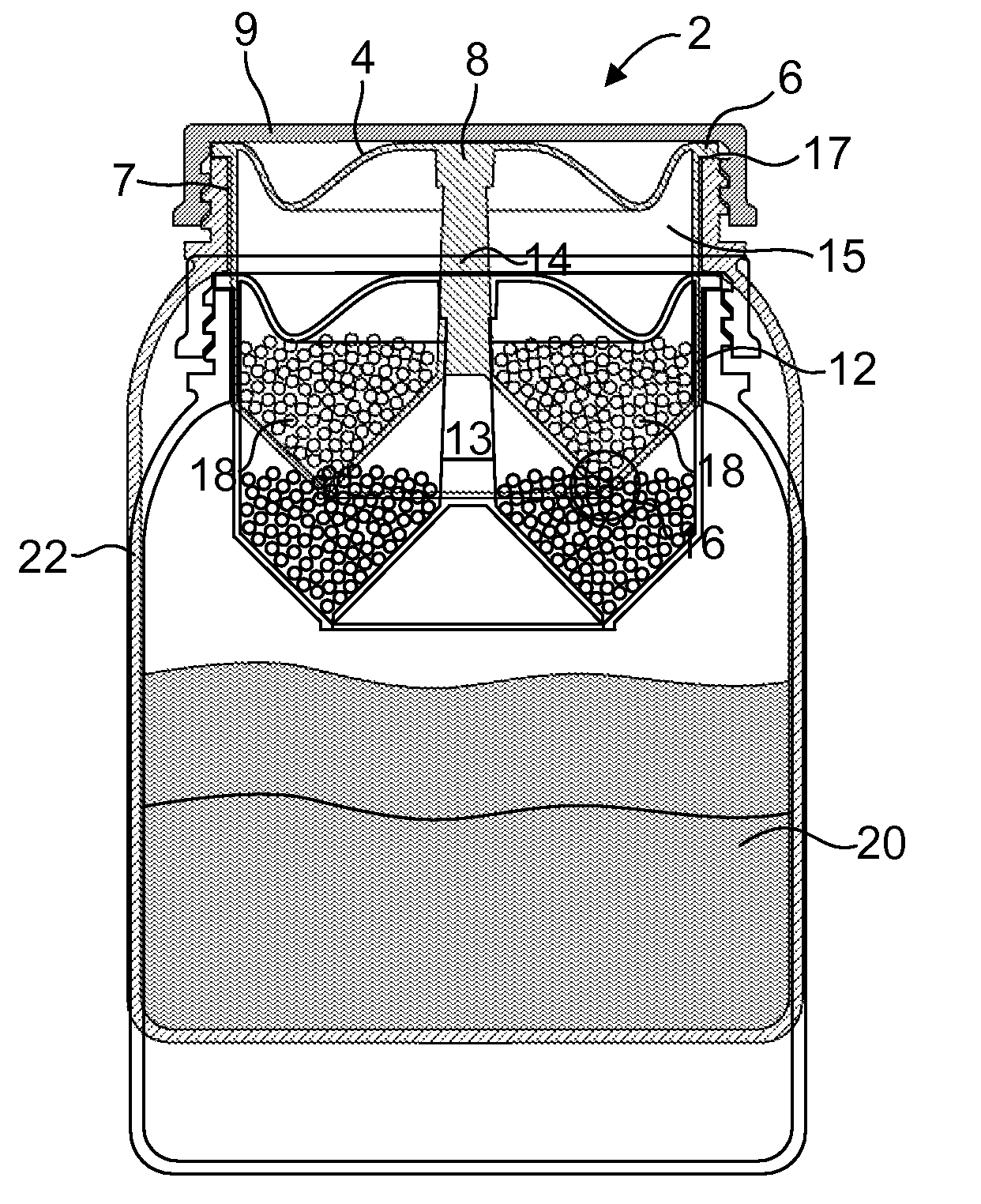
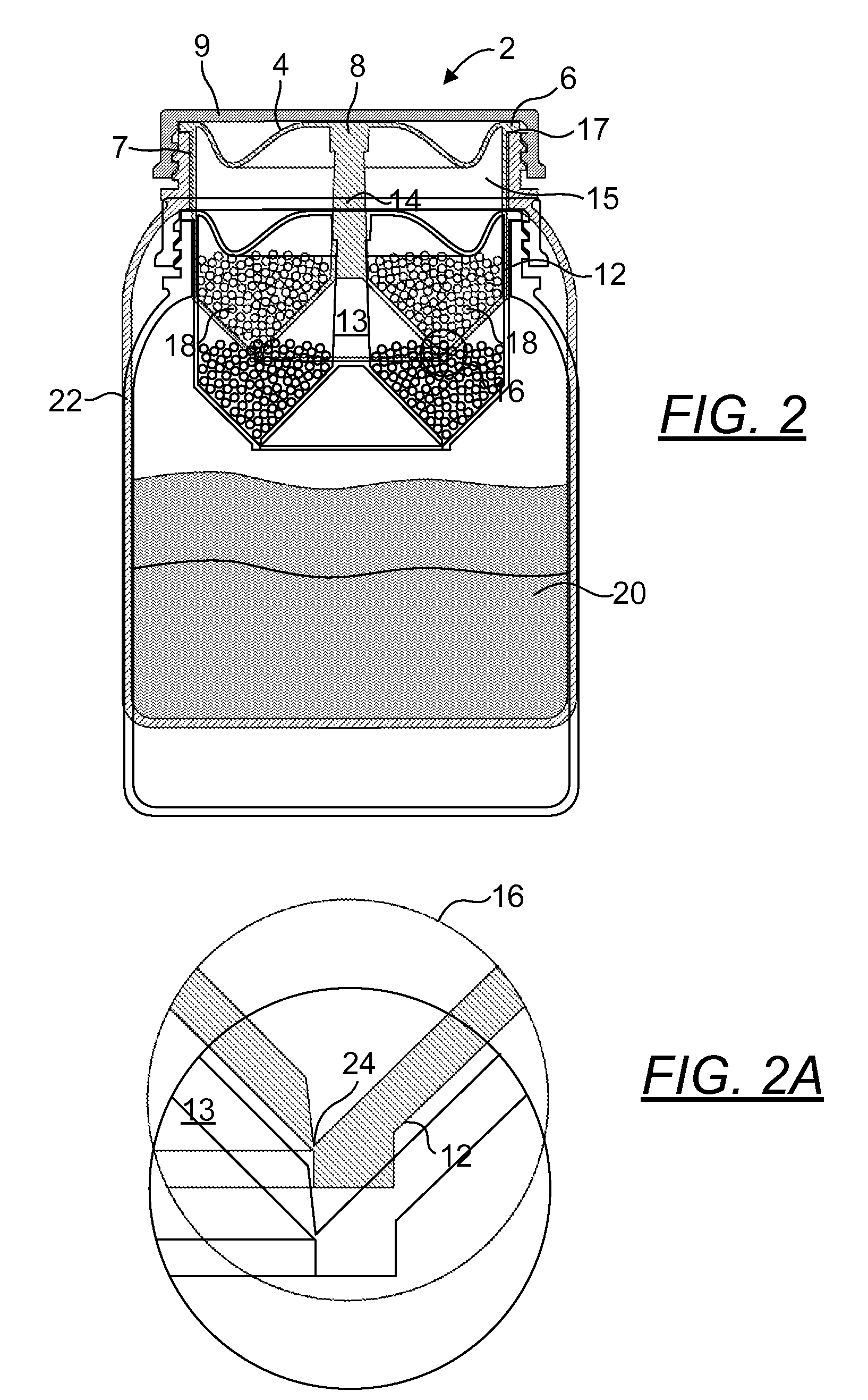
[0155]The use of conventional liquid containers such as plastic bottles for carrying water, juices, and other desirable liquids for human consumption is quite well known. The present device is generally directed to a dispensing capsule that may be used with such bottles or containers to separately store an ingredient to be mixed with a liquid at the time of consumption to form a consumable solution. In describing the preferred and alternate embodiments of the present device, as illustrated in the Figures, specific terminology is employed for the sake of clarity. The invention, however, is not intended to be limited to the specific terminology so selected, and it is to be understood that each specific element includes all technical equivalents that operate in a similar manner to accomplish similar functions.

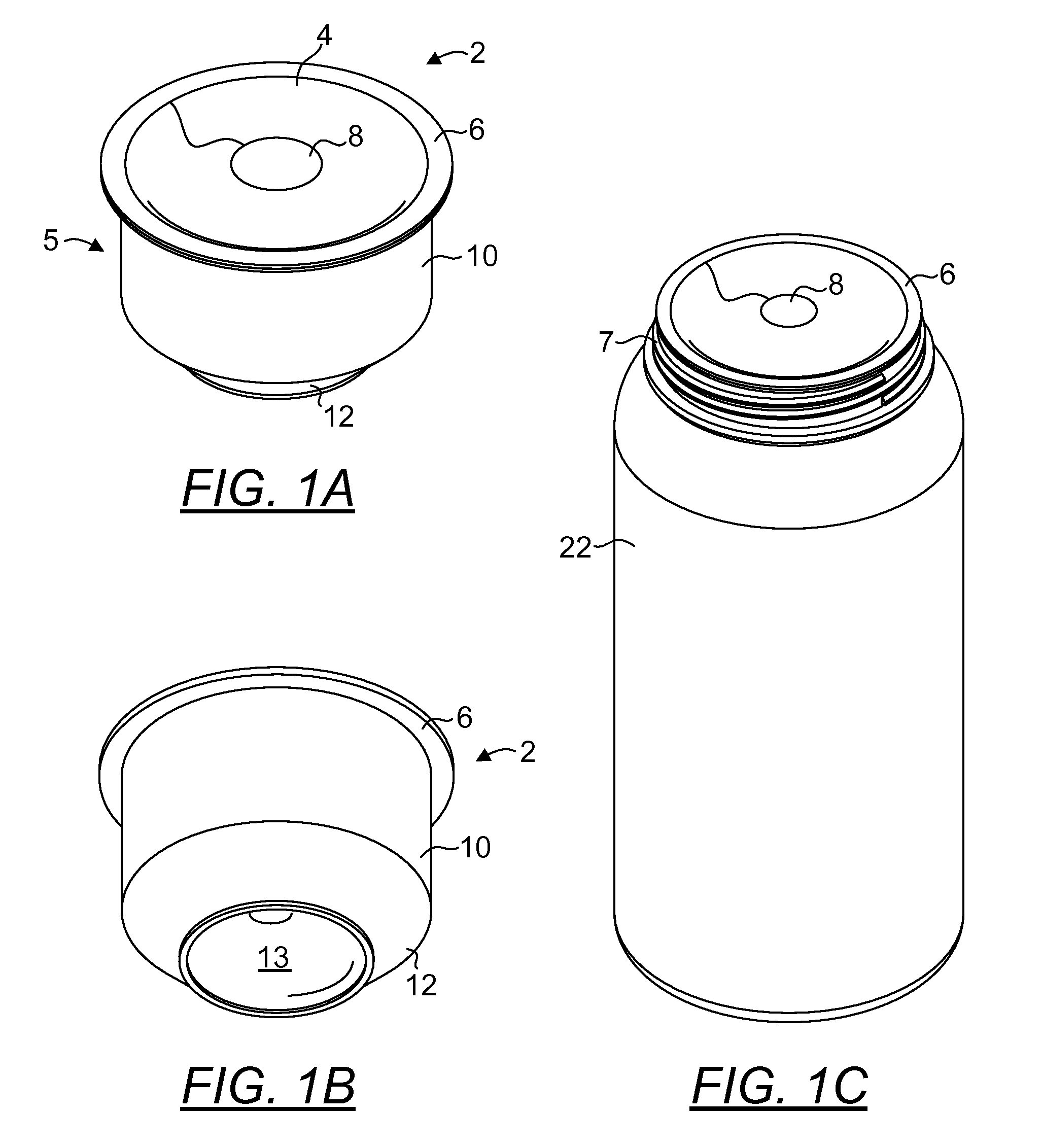
[0156]FIG. 1A is a top perspective view, and FIG. 1B is a bottom perspective view, of one embodiment of a dispensing capsule 2 of the present device. In this embodiment, the dispe...


PUM


Abstract

A dispensing capsule and method for use thereof, wherein the dispensing capsule is preferably pre-loaded during time of manufacture with a selected dry or liquid ingredient to facilitate subsequent consumer use. The dispensing capsule comprises an apertured housing removably-engagable to the opening of a bottle or container containing a fluid. Preloaded ingredients contained within a cavity in the housing may be introduced or discharged into the bottle by simply depressing a button on the diaphragm of the housing, thereby actuating a breakaway plunger to open an aperture in the opposing base plate of the housing, permitting the contents to flow through the aperture and into the liquid contents of the bottle. The combined contents and liquid within the bottle may subsequently be agitated (e.g., shaken or mixed) without fear or risk of leakage or spillage. A hand held dispensing capsule is also disclosed.

Description

TECHNICAL FIELD[0001]The present device relates generally to dispensing capsules, and more specifically, to a dispensing capsule for removable engagement with a liquid-containing bottle and enabling dry or liquid ingredients contained within the dispensing capsule to be conveniently deposited into a bottle and mixed with the liquid contents thereof. A hand held dispensing capsule is also provided.BACKGROUND OF THE INVENTION[0002]The movement to decrease transportation costs, packaging size, environmental waste and valuable store shelf space has increased the demand for innovative packaging for a wide range of products. Many products are sold as liquid concentrates, crystals and powders to be mixed with a liquid prior to consumption or use. Such products include foods, drugs, cosmetics, adhesives, polishes, cleansers, dyes, infant formula, drink mixes, meal replacements, protein powders, energy mixes, supplements, nutritional products and other substances. Some of these products do n...

Claims


Application Information

Patent Timeline
Patent Type & Authority Applications(United States)
IPC IPC(8): B65D25/08
CPCB65D81/3222B65D25/085
Inventor COON, DARREN
Owner GENESEE REGIONAL BANK
Why Eureka
Try Eureka