Tool cases with easy removal of stored items

a tool case and storage box technology, applied in the field of tool cases, can solve the problems of difficult removal of stored items, and achieve the effect of convenient removal of stored items and convenient storag

Inactive Publication Date: 2010-08-12
TEAM FAIR HLDG
View PDF19 Cites 6 Cited by
  • Summary
  • Abstract
  • Description
  • Claims
  • Application Information

AI Technical Summary

Benefits of technology

[0003]It is an object of the invention to improve on existing tool cases and provide tool cases and tool case features which facilitate secure storage and yet easy removal of stored items.
[0006]In a variation, a lever is preferably pivotably connected to a side of the base and extends across the stop plate and protrudes through an opposite side of the base via a J-shaped opening providing a manual means to raise and lower the stop plate, so that when the lid is open, an end of the lever is pushed along the J slot and inserted in a short end of the opening to thereby retain the lever and lowering the stop plate and the fingers making the components easily accessible, and when the lid is closed, a tapered projection on an edge of the lid urges the lever out of the short end of the opening and the stop plate is biased towards the lid, causing the fingers to extend through the panel to provide stops for the components.

Problems solved by technology

Because the stored items generally must be somehow secured so that they do not accidentally move around within the case or fall out of the case when the case is opened, the stored items are often difficult to remove.

Method used


Image

  • Tool cases with easy removal of stored items
  • Tool cases with easy removal of stored items
  • Tool cases with easy removal of stored items

Examples


second embodiment

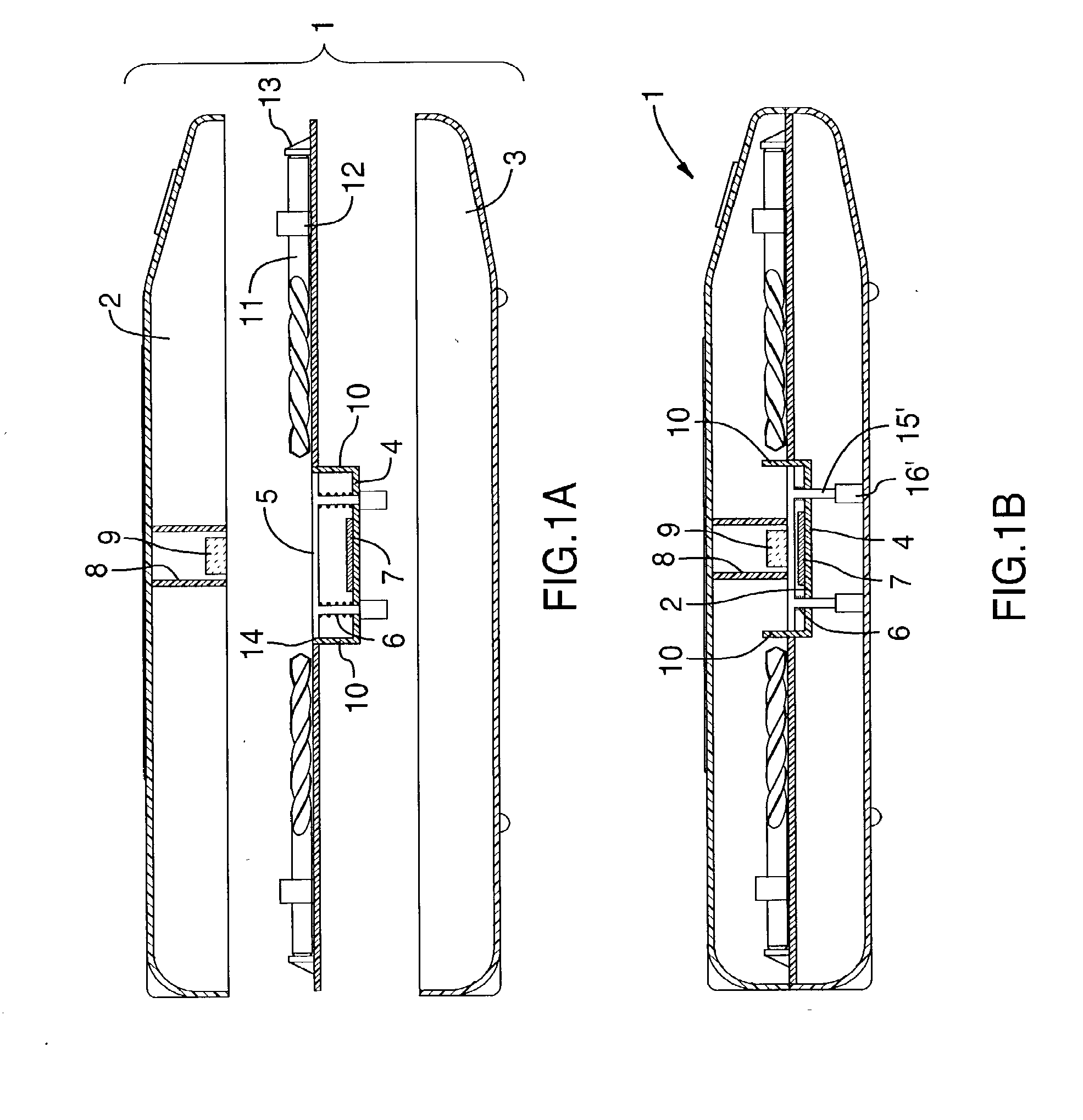
[0076]FIGS. 2A to 2C show a second embodiment, having a floating panel 5′ arranged between the top lid 2 and base portion 3. The panel has hollow protrusions 16 which receive posts 15, preferably molded into the base 3 and the panel is supported by biasing means 6, for example springs. There are stops 10′ preferably integrally molded in the base that reach the height of the panel when the lid is open and the panel is fully pressed away from the base by the biasing means. When the lid is closed, ribs 17 preferably molded on the inside of the lid press the panel towards the base and the tip of the stops 10′ protrude through slots 18 in the panel to act as further end stops for the components (similar to the fingers described above). Thus, when the lid is open, the panel is urged upwards and clears the stops molded in the base facilitating removal of components, as the lid is closed, the ribs inside the lid depress the panel exposing the stops beyond the ends of the components making i...

third embodiment

[0077]FIGS. 3A to 3B show a third embodiment, having a panel 5″ between the top lid 2 and base portion 3. Fixed end stops 13 are used to prevent the components 11 from sliding too much in the panel. The end stops are preferably molded in the panel. The component is placed on the panel and held in place by a combination of a clip 12′ and a bridge 12. The bridge is used to align the component during insertion into the tool case / clip. Beneath one end 11′ of the components are depressions 19 in the panel 5″. To remove a component, the one end 11′ is pushed down into the depression. This elevates the opposite end of the component, freeing it from the clip 12′ but still restrained by the bridge 12. The component can then be easily pulled out for use.

[0078]FIGS. 4A to 4B show a fourth embodiment of a tool case 1 similar to the third embodiment. Some end stops 13′ are not part of the panel, but rather a double-walled construction is used on the lid. This provides immobility for the part whe...

eighth embodiment

[0083]FIGS. 8A to 8F show an The panel has recesses (omitted for clarity) accommodating at least one pivotable holder 26. Components 11 are placed in the pivotable holder, which is then attached to the panel by means of pivot pins 27 (preferably molded on the sides of the pivotable holder) and mounting holes (not shown) through side walls 28 of the recesses. The pivot points are located such that the holder 26 pivots up to expose the components in their free position, when the lid 2 is open. The holder preferably have an enclosed end 29, an open end 30 and a hold down bar 31. The components are inserted into the holder via the open end and securely held by the enclosed end in cooperation with the hold down bar. The holder further has an extension arm 32, preferably integrally molded with the holder, on one side of said holder protruding from the open end 30. The lid has an activation ridge 33, preferably integrally molded with the lid, on an inside edge of the lid. Upon closing, th...


PUM


Abstract

A tool case has a lid and a base, and a panel arranged therebetween. Various structures are used to trap or otherwise retain tools, tool items or other stored items, such that they cannot accidentally fall out of their “home” positions, but such that they are readily removable by the user when desired. Such structures include, for example, retractable stops, depressions beneath stored items, weight-biased pivoting of holders, spring biasing of holders, trapping of items by the lid or by other item holders within the case, and various clip arrangements. Preferably the lid is transparent, and the tools or other items are arranged by height in step-wise fashion, the panel being stepped accordingly, to maximize visibility.

Description

CROSS REFERENCE TO RELATED APPLICATIONS[0001]This application is a division of U.S. patent application Ser. No. 10 / 188,830, filed Jul. 5, 2002, which claims the benefit of priority of U.S. Provisional Patent Application No. 60 / 302,704, filed Jul. 5, 2001, both of which are incorporated herein by reference in their entirety.BACKGROUND OF THE INVENTION[0002]This invention relates to tool cases, particularly those which hold a variety of items, and particularly to features which provide easy access to those items. It is common to store tools, tool bits, drill bits or other items in tool cases, usually by some sort of snap-in arrangement or similar. Because the stored items generally must be somehow secured so that they do not accidentally move around within the case or fall out of the case when the case is opened, the stored items are often difficult to remove.SUMMARY OF THE INVENTION[0003]It is an object of the invention to improve on existing tool cases and provide tool cases and too...

Claims


Application Information

Patent Timeline
Patent Type & Authority Applications(United States)
IPC IPC(8): B25H3/02B25H3/00
CPCB25H3/003B25H3/023B25H3/02
Inventor VASUDEVA, KAILASH C.
Owner TEAM FAIR HLDG
Why Eureka
Try Eureka