Top-Emission Organic Light-Emitting Devices with Microlens Arrays

a technology of organic light-emitting devices and micro-lens arrays, which is applied in the direction of discharge tubes/lamp details, discharge tubes luminescnet screens, electric discharge lamps, etc., can solve the problems of low light outcoupling efficiency, and the method does not have any effect on ito/organic waveguide modes, so as to enhance outcoupling efficiency, enhance outcoupling efficiency, and enhance outcoupling efficiency in oleds

Inactive Publication Date: 2010-08-12
UNIV OF FLORIDA RES FOUNDATION INC
View PDF6 Cites 26 Cited by
  • Summary
  • Abstract
  • Description
  • Claims
  • Application Information

AI Technical Summary

Benefits of technology

[0005]Embodiments of the invention can provide organic light-emitting devices (OLEDs) with enhanced outcoupling efficiency. Specific embodiments can enhance the outcoupling efficiency by more than four times.
[0006]Embodiments of the invention incorporate microlens arrays on the emitting surface of a top-emission OLED. Incorporation of microlens arrays on the emitting surface of a top-emission OLED can greatly enhance the outcoupling efficiency in OLEDs. FIG. 2 shows a specific embodiment of a top-emission OLED utilizing microlens arrays on the emitting surface. Different from the more conventional bottom-emission OLEDs, in the top-emission device, all the light emission generated in the organic layers is now accessible by modifications at the light-emitting surface. With a microlens array attached to the emitting surface, much of, if not all, of the waveguiding modes can be extracted. The microlens array can be fabricated using the inkjet printing method or using other methods, including molding. Preferably, no damage, or negligible damage, is imposed upon the device during the microlens array fabrication / attachment process.

Problems solved by technology

Typically, only about 20% of the energy is contained in the external modes, suggesting a very low light outcoupling efficiency.
This method, however, does not have any effect on the ITO / organic-waveguiding modes as these layers are spatially separated from the microlenses by the substrate.

Method used


Image

  • Top-Emission Organic Light-Emitting Devices with Microlens Arrays
  • Top-Emission Organic Light-Emitting Devices with Microlens Arrays
  • Top-Emission Organic Light-Emitting Devices with Microlens Arrays

Examples


Embodiment Construction

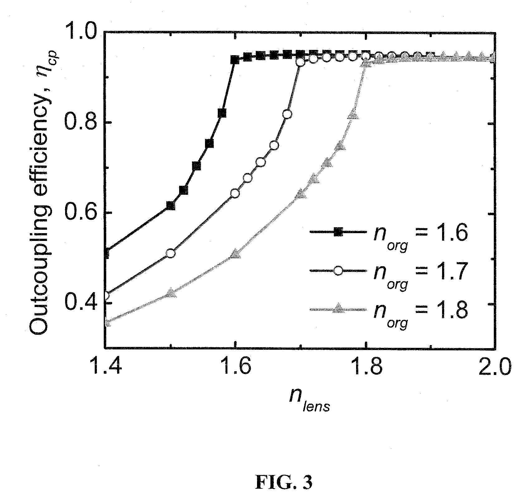
[0013]Embodiments of the invention can provide organic light-emitting devices (OLEDs) with enhanced outcoupling efficiency. Specific embodiments can enhance the outcoupling efficiency by more than four times.

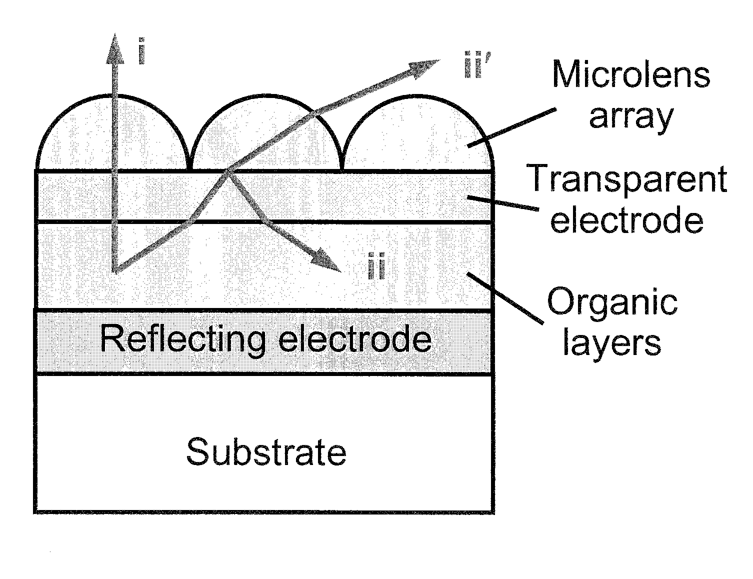
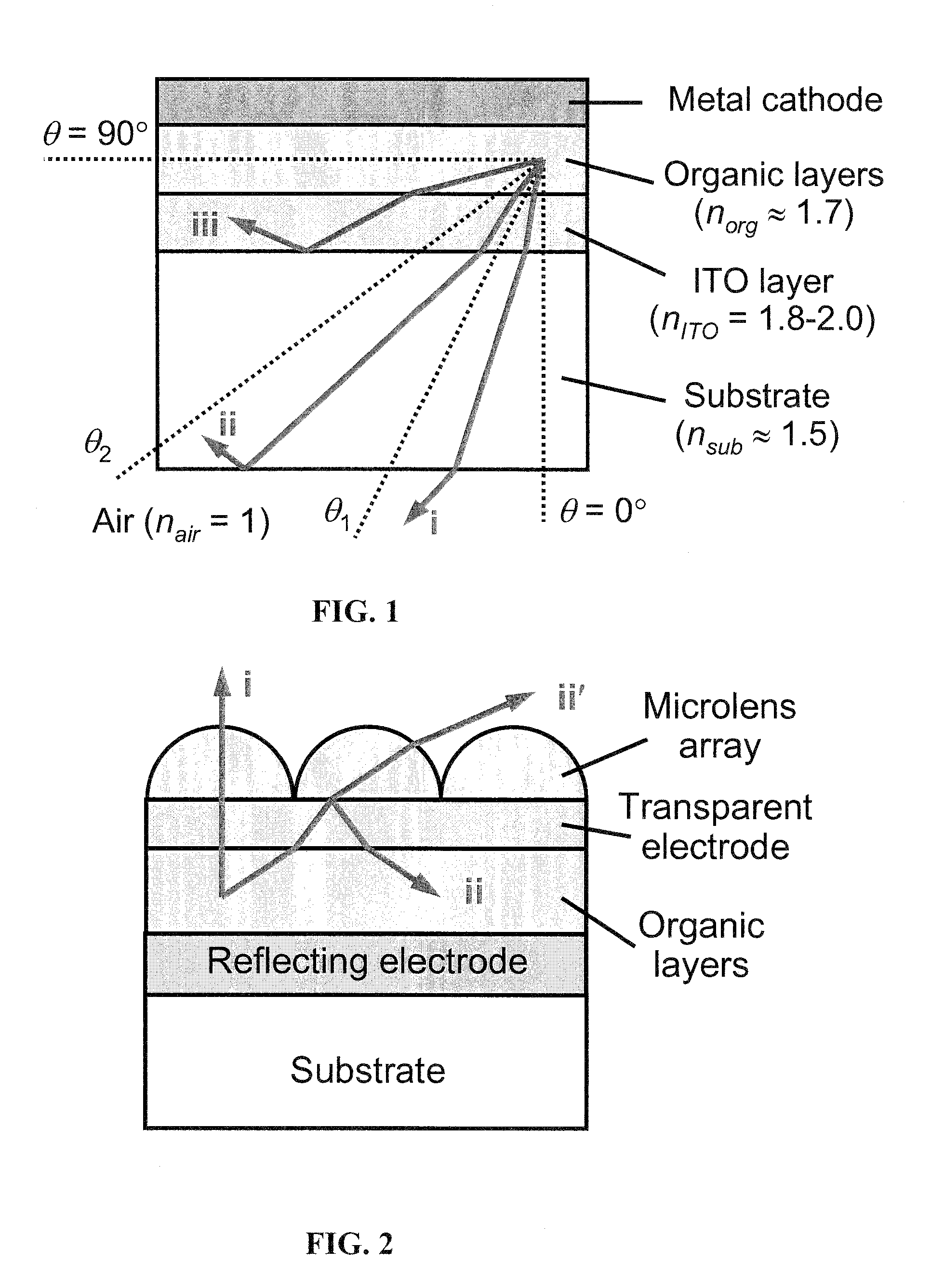
[0014]Embodiments of the invention incorporate microlens arrays on the emitting surface of a top-emission OLED. Incorporation of microlens arrays on the emitting surface of a top-emission OLED can greatly enhance the outcoupling efficiency in OLEDs. FIG. 2 shows a specific embodiment of a top-emission OLED utilizing microlens arrays on the emitting surface. The top-emission OLED shown in FIG. 2 incorporates a substrate, a reflecting electrode, organic layers, a transparent electrode, and a microlens array. The transparent electrode can have a thickness in the range of 20 nm to 150 nm, and preferably 50 nm-100 nm. The reflecting electrode can be made of, for example, a metal such as aluminum or silver. Alternatively, the reflecting electrode can be a dielectric mirror with a tran...


PUM


Abstract

Embodiments of the invention can provide organic light-emitting devices (OLEDs) with enhanced outcoupling efficiency. Specific embodiments can enhance the outcoupling efficiency by more than four times. Embodiments of the invention incorporate microlens 5 arrays on the emitting surface of a top-emission OLED. Incorporation of microlens arrays on the emitting surface of a top-emission OLED can greatly enhance the outcoupling efficiency in OLEDs. With a microlens array attached to the emitting surface, much of, if not all, of the waveguiding modes can be extracted. The microlens array can be fabricated using the inkjet printing method or using other methods, including molding.

Description

CROSS-REFERENCE TO RELATED APPLICATION [0001]The present application claims the benefit of U.S. Provisional Application Ser. No, 60 / 948,814, filed Jul. 10, 2007, which is hereby incorporated by reference herein in its entirety, including any figures, tables, or drawings.BACKGROUND OF INVENTION [0002]Organic light-emitting devices (OLEDs) are now being commercialized for use in flat-panel displays and as solid-state lighting sources. The internal quantum efficiency of some state-of-the-art OLEDs can be nearly 100%. However, due to the refractive indices of the organic layers and the substrate being higher than the refractive index of air, the light generated in the organic emissive region can be emitted into three modes as shown in FIG. 1. These three modes include: (i) external modes, which can escape through the substrate; (ii) substrate-waveguiding modes, which extend from the substrate / air interface to the metal cathode; and (iii) ITO / organic-waveguiding modes, which are confined...

Claims


Application Information

Patent Timeline
Patent Type & Authority Applications(United States)
IPC IPC(8): H01L51/52
CPCH05B33/22
Inventor XUE, JIANGENGDOUGLAS, ELLIOT PAUL
Owner UNIV OF FLORIDA RES FOUNDATION INC
Why Eureka
Try Eureka