
Hybrid balun apparatus

a balun and hybrid technology, applied in the direction of electrical devices, multi-port networks, balance-unbalance networks, etc., can solve the problems of loss of signal, power waste, linearity worse than that of passive elements,

Inactive Publication Date: 2010-08-12
ELECTRONICS & TELECOMM RES INST
View PDF8 Cites 24 Cited by
  • Summary
  • Abstract
  • Description
  • Claims
  • Application Information

AI Technical Summary

Benefits of technology

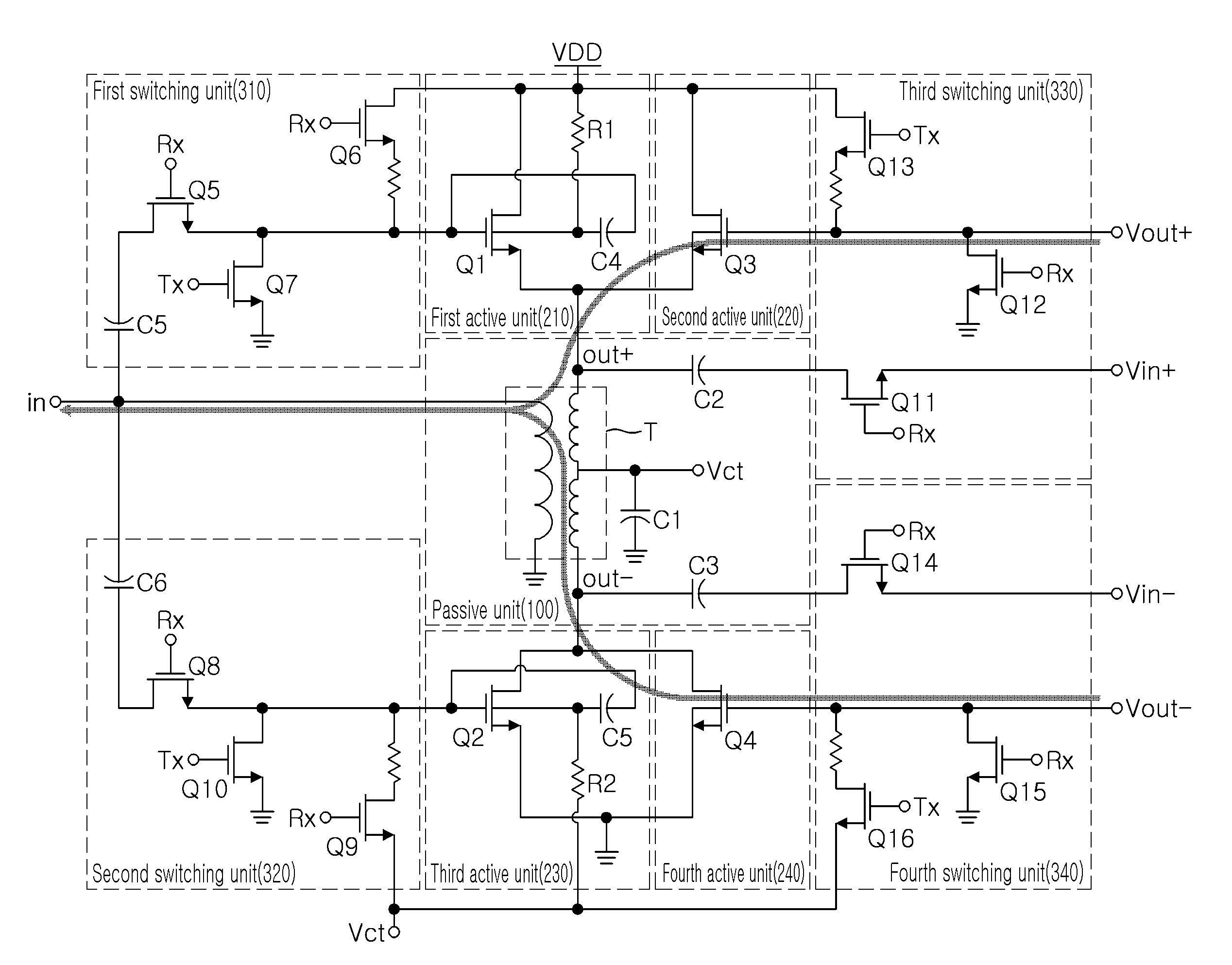
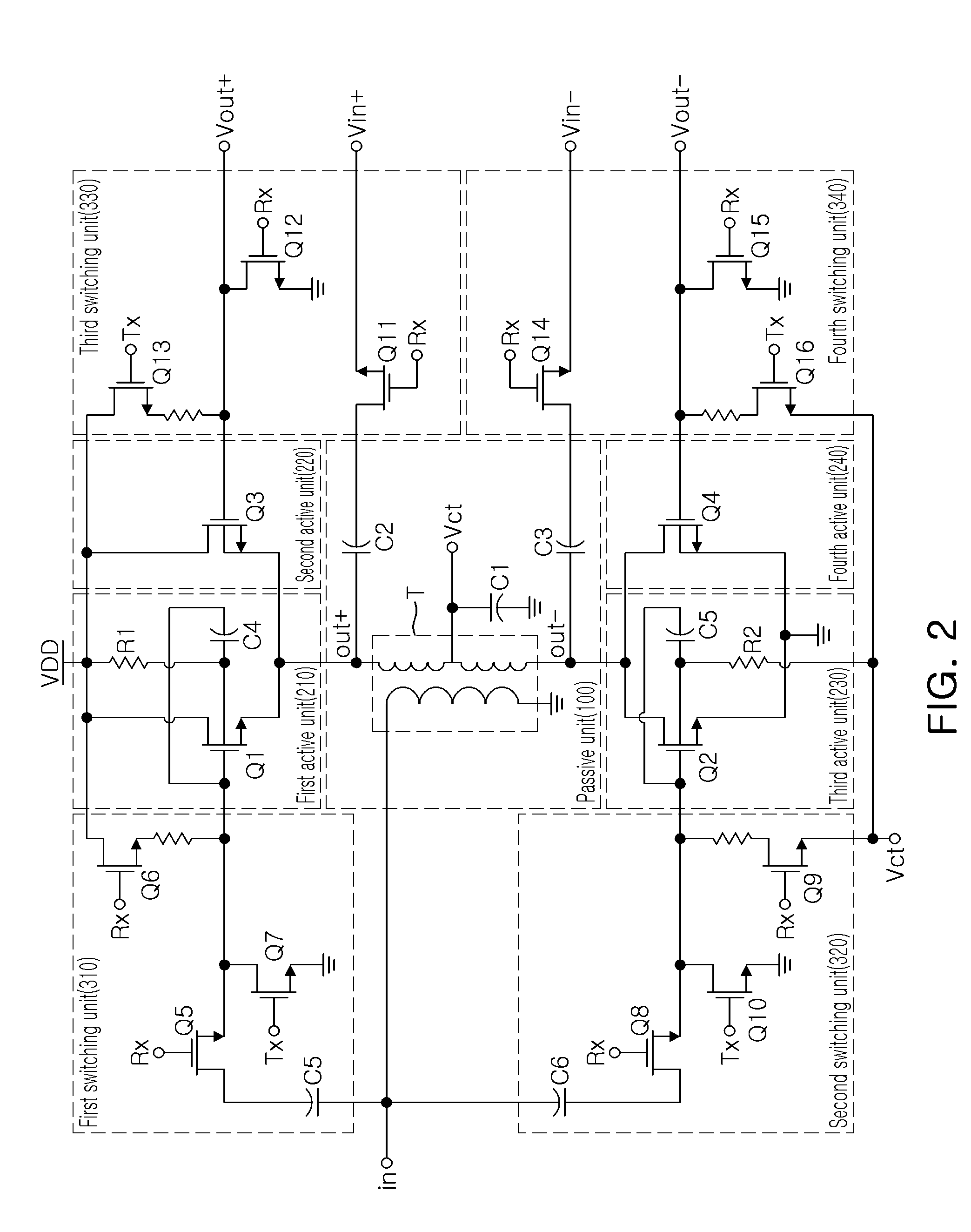
[0017]An aspect of the present invention provides a hybrid balun apparatus capable of supporting both reception mode and transmission mode and being advantageous for a high level of integration, by integrating a T / R switch and a balun and replacing two transformers disposed at a reception path and a transmission path with a single transformer.

Problems solved by technology

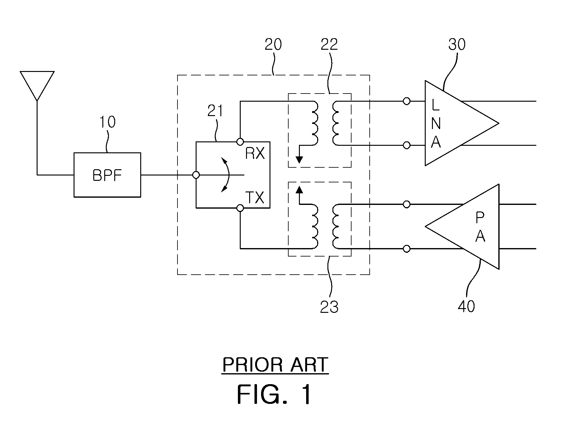
Such a passive element has good linearity but with a loss of signal.
An active element is designed with a CMOS transistor to generate differential signals having the same signal size but with a phase difference of 180°, which has a relatively good gain but is disadvantageous in that power is wasted and its linearity is worse than that of the passive element.
However, the two transformers provided at the reception path and the transmission path, respectively, occupy a relatively larger area, impeding a high level of integration of the hybrid balun apparatus.
In addition, when the signal passes through the T / R switch, a great deal of loss occurs in the signal, and it is noted that isolation characteristics between the reception path and the transmission path, and the like, are degraded in comparison with the performance of a commercial chip.

Method used


Image

  • Hybrid balun apparatus
  • Hybrid balun apparatus
  • Hybrid balun apparatus

Examples


Embodiment Construction

[0040]Exemplary embodiments of the present invention will now be described in detail with reference to the accompanying drawings. The invention may however be embodied in many different forms and should not be construed as limited to the embodiments set forth herein. Rather, these embodiments are provided so that this disclosure will be thorough and complete, and will fully convey the scope of the invention to those skilled in the art.

[0041]In the drawings, the shapes and dimensions may be exaggerated for clarity, and the same reference numerals will be used throughout to designate the same or like components.

[0042]In addition, unless explicitly described to the contrary, the word “comprise” and variations such as “comprises” or “comprising,” will be understood to imply the inclusion of stated elements but not the exclusion of any other elements.

[0043]Exemplary embodiments of the present invention will now be described with reference to the accompanying drawings.

[0044]FIG. 2 illustr...


PUM


Abstract

A hybrid balun apparatus are disclosed. The hybrid balun apparatus can support both the reception mode and the transmission mode and be advantageous for a high level of integration, by replacing two transformers disposed at a reception path and a transmission path with a single transformer and integrating a T / R switch and a balun into a one chip. Therefore, an IC according to integration extends to a front stage of an antenna to facilitate interfacing between elements, and a burden for designing at a rear stage (i.e., LNA in the reception mode, and PA in the transmission mode) can be reduced.

Description

CROSS-REFERENCE TO RELATED APPLICATIONS[0001]This application claims the priorities of Korean Patent Application Nos. 10-2009-0010524 filed on Feb. 10, 2009, and 10-2009-0039866 filed on May 7, 2009 in the Korean Intellectual Property Office, the disclosures of which are incorporated herein by reference.BACKGROUND OF THE INVENTION[0002]1. Field of the Invention[0003]The present invention relates to a hybrid balun apparatus and, more particularly, to a hybrid balun apparatus supporting both reception and transmission modes and being advantageous for a high level of integration.[0004]2. Description of the Related Art[0005]In the past, RF baluns and transmission / reception switches (T / R SW) were separately designed or integrated, rather than being designed as a one chip.[0006]RF baluns are divided into an RF balun designed with a passive element and an RF balun designed with an active element.[0007]A passive element commonly uses a structure with a transformer, and structures of actuall...

Claims


Application Information

Patent Timeline
Patent Type & Authority Applications(United States)
IPC IPC(8): H01P5/22H03H7/42
CPCH03H11/32
Inventor LEE, YOUNG JAEKIM, CHEON SOOYU, HYUN KYU
Owner ELECTRONICS & TELECOMM RES INST
Learn More