
Optical Touch Display Device and Method Thereof

Active Publication Date: 2010-08-12
QUANTA COMPUTER INC
View PDF20 Cites 35 Cited by
  • Summary
  • Abstract
  • Description
  • Claims
  • Application Information

AI Technical Summary

Benefits of technology

[0007]Accordingly, a scope of the present invention is to provide an optical touch display device using a multi-points touch technology and a specific touch gesture to generate a corresponding controlling to achieve the aim of control. In this way, the optical touch display device of the invention is more humanized to simplify the inputting operation to solve the problems in prior art.
[0009]Another scope of the present invention is to provide a method of operating an optical touch display device using a multi-point touch technology and a specific touch gesture to generate a corresponding controlling to achieve the aim of control. In this way, the optical touch display device of the invention is more humanized to simplify the inputting operation to solve the problems in prior art.

Problems solved by technology

However, in practical applications, the user always carelessly lays two or more fingers on the monitor, so the conventional image processing technology is unable to judge or even mis-operate.

Method used


Image

  • Optical Touch Display Device and Method Thereof
  • Optical Touch Display Device and Method Thereof
  • Optical Touch Display Device and Method Thereof

Examples


Embodiment Construction

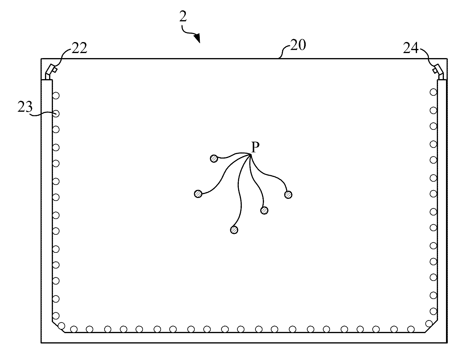
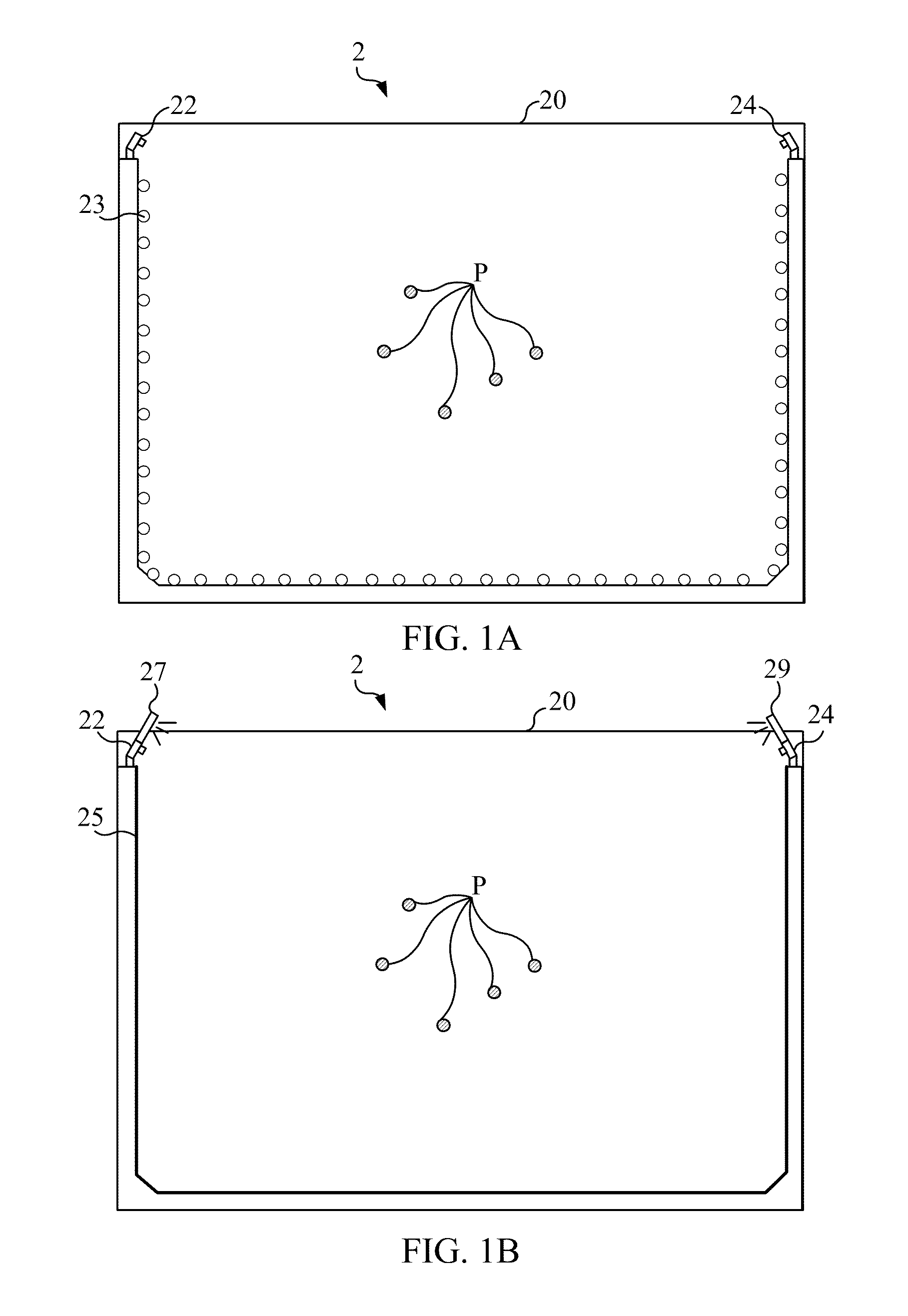
[0023]Please refer to FIG. 1A. FIG. 1A illustrates a schematic diagram of the optical touch display device 2 in an embodiment of the invention. The optical touch display device 2 includes a display module 20, a first image capturing module 22, a second image capturing module 24, and a plurality of lighting units 23. In fact, the optical touch display device 2 can also include a processing module (not shown in the figure). As shown in FIG. 1A, the optical touch display device 2 of the invention can be used to recognize a plurality of touch points P and perform a corresponding specific action or function. The plurality of lighting units 23, which are located around the display module 20, is used to generate light for the optical touch display device 2 to perform the touching recognition.

[0024]FIG. 1B illustrates another type of the optical touch display device 2. As shown in FIG. 1B, the optical touch display device 2 includes not only a display module 20, a first image capturing modu...


PUM


Abstract

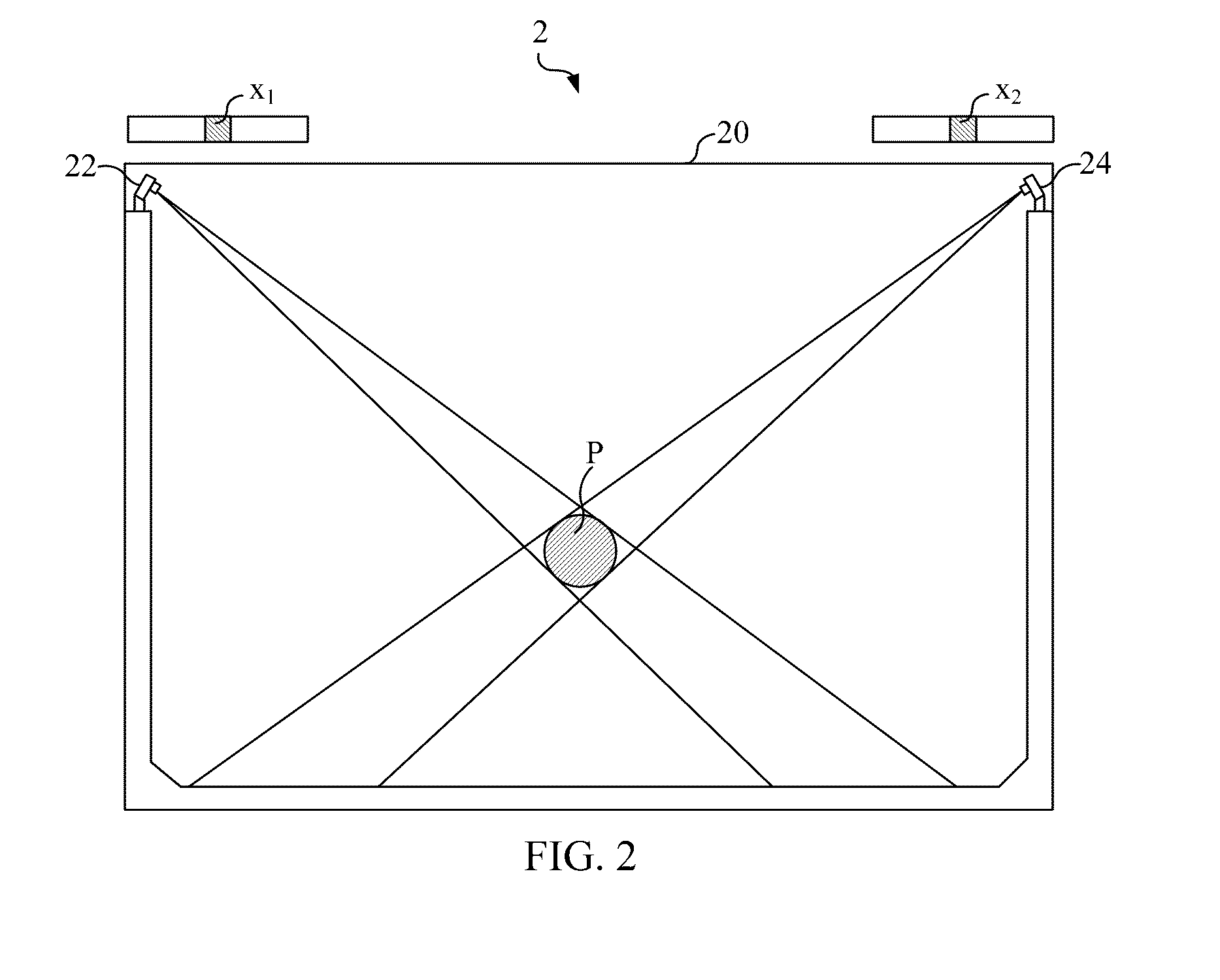
The invention provides an optical touch display device. The optical touch display device comprises a display module, a first image capturing module, a second image capturing module and a processing module. The display module generates N touch points according to a touch gesture, the touch gesture has a specific moving model, and N is a positive integer. The first image capturing module retrieves a first image relating to N touch points. The second image capturing module retrieves a second image relating to N touch points. The processing module determines correspondingly a specific touch chord of N touch points according to the first image and the second image, and determines correspondingly a specific function of the touch gesture according to the specific touch chord and the specific moving mode.

Description

BACKGROUND OF THE INVENTION[0001]1. Field of the Invention[0002]The present invention generally relates to a touch display apparatus, and more particularly, to the optical touch display device which can recognize the gesture to perform a multi-point touch inputting.[0003]2. Description of the Prior Art[0004]In recent years, with the vigorous development of image display technology, the touch panel has already become an important feature for an electronic product of the related companies because the touch panel has an interactive human machine interface (HMI) for users to input directly, for example, a point of sale (POS) terminal, a voting machine, a lottery machine, an industrial automation, a medical equipment, an office automation, a retail automation, a drugs manufacture automation, or a satellite navigational system of the vehicle. The integration of the monitor and the touch control technology of the electrical product can increase the value of the product; it is not only an i...

Claims


Application Information

Patent Timeline
IPC IPC(8): G06F3/041
CPCG06F3/0428G06F3/017
Inventor HUANG, YI-MINGCHIANG, CHING-CHUNLIU, YUN-CHENGLIOU, CHIOU-TZUNGCHANG, TING-HSUAN
Owner QUANTA COMPUTER INC
Learn More