Forearm rotation mechanism and orthesis which includes such a mechanism

a technology of forearm rotation and orthesis, which is applied in the field of forearm rotation mechanism and orthesis or exoskeleton, can solve the problems of difficulty in realising these devices, difficulty in realising longitudinal axes,

Active Publication Date: 2010-08-12
COMMISSARIAT A LENERGIE ATOMIQUE ET AUX ENERGIES ALTERNATIVES
View PDF17 Cites 85 Cited by
  • Summary
  • Abstract
  • Description
  • Claims
  • Application Information

AI Technical Summary

Benefits of technology

[0012]Consequently it is an objective of the present invention to provide an orthesis with small overall dimensions, of low mass, which exhibits low inertia and which is quick and simple to fit.PRESENTATION OF THE INVENTION
[0049]Advantageously the return pulleys have the same axis as that of one of the pivot links in order to prevent any variation in the length of the cable.

Problems solved by technology

Several difficulties are encountered, however, in the realisation of these devices.
On the one hand, although it is easy to reproduce transverse rotations by making a mechanical axis of rotation coincide with the axis or pseudo-axis of the anatomical rotation, it is however much less easy to realise longitudinal axes (in the case, for example, of arms or forearms).
This solution prevents easy fitting and rapid release, something which is even more marked for an individual who is handicapped.
Furthermore this solution might not be viable for safety reasons.
In addition, the means of actuation are not offset, which makes these segments even heavier.
This orthesis is therefore cumbersome, with a significant mass and significant inertia.
Furthermore the confinement of the forearm can rule out this solution.
Although this orthesis does not have the drawback of being confining, the beam supporting the guide is, however, of significant mass in order to support the weight of the guide and withstand bending forces.
This orthesis is therefore cumbersome and heavy and exhibits significant inertia.
In previous mechanisms, the lever arm produces a significant bending moment, which causes very high levels of local stress on the guide rail and hence friction which hinders movements.
With designs using the current state of the technique, however, their mass is made to rotate, which involves significant inertia.

Method used


Image

  • Forearm rotation mechanism and orthesis which includes such a mechanism
  • Forearm rotation mechanism and orthesis which includes such a mechanism
  • Forearm rotation mechanism and orthesis which includes such a mechanism

Examples


Embodiment Construction

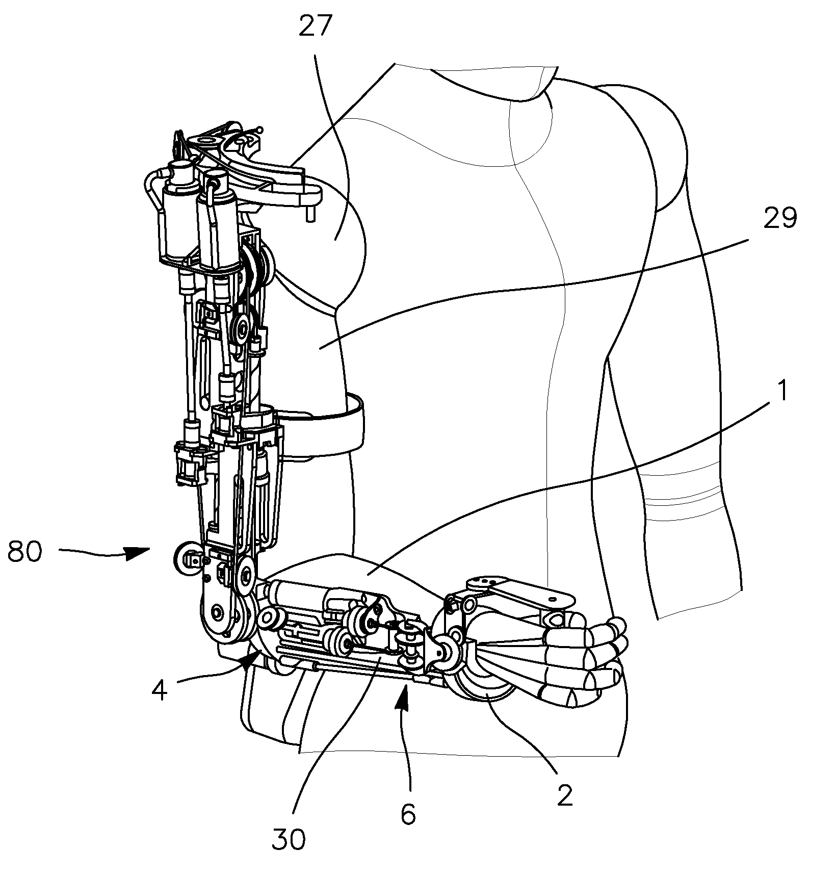
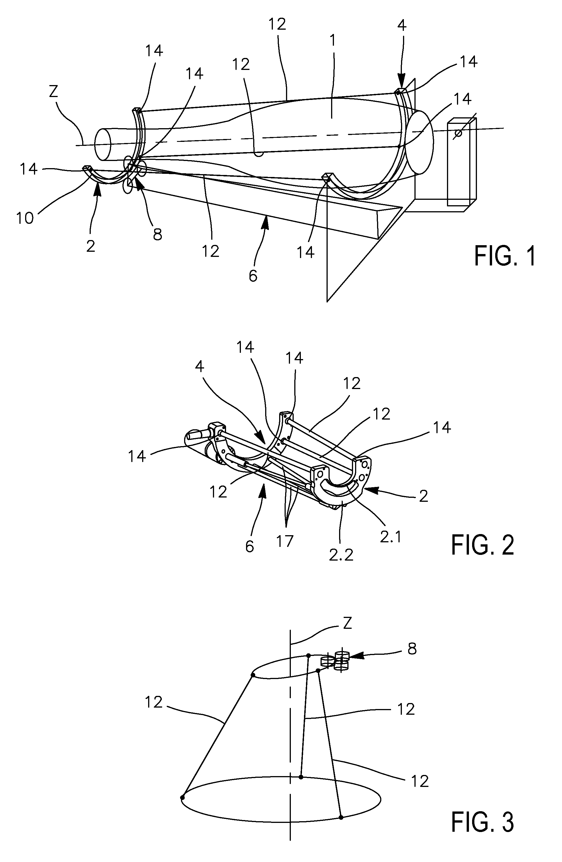
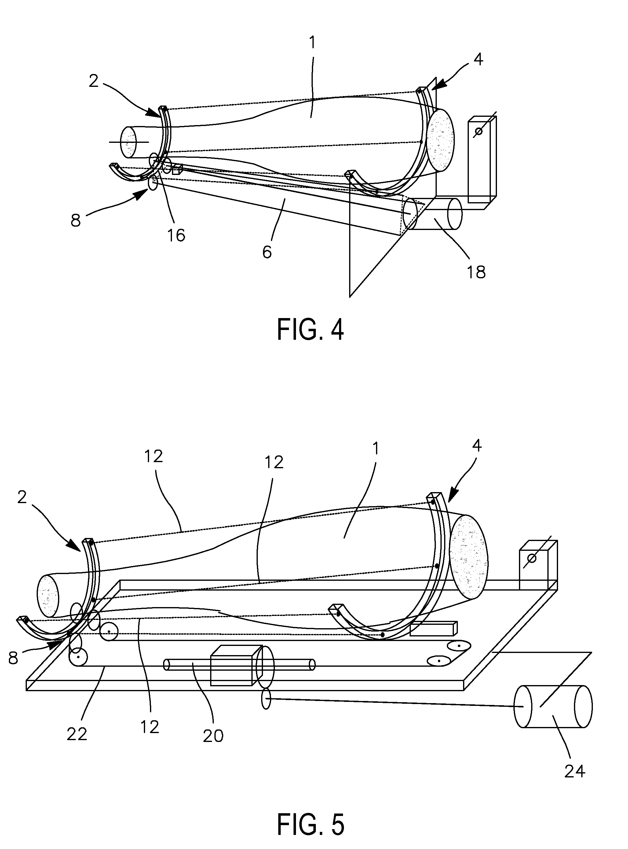
[0071]The mechanism of rotation for the forearm orthesis according to the present invention is designed to hold a forearm 1, where the longitudinal axis of the forearm 1 is approximately the same as that of the mechanism.

[0072]The terms > and > are to be used by analogy with the front and rear of the forearm. Thus front will correspond to the end designed to be at the hand end and the rear corresponds to the end designed to be at the elbow end.

[0073]The mechanism represented in FIG. 1 includes a front stay 2, a rear stay 4 and a rigid strut 6 which connects the front stay 2 and rear stay 4.

[0074]The front stay 2 or moving stay takes the form of a portion of the arc of a circle designed to be mounted so that it moves on the strut 6. The moving stay 2 is designed to pivot in a plane P which is approximately orthogonal to the axis of the forearm around a longitudinal axis Z which is approximately co-linear with that of the fore-arm 1.

[0075]The moving stay 2 is fitted so that it moves o...


PUM


Abstract

Rotation mechanism for a forearm which includes a moving stay (2) which supports a wrist, which includes at least one guide track in the form of an arc of a circle, a fixed stay (4) which supports the rear end of a forearm, rods (12) that are rigid lengthwise which link the moving stay (2) and the fixed stay (4) and which allow the moving stay (2) and fixed stay (4) to rotate around a longitudinal axis (Z), by means of articulated links which can rotate (14), and a strut (6) rigidly linked at one of its ends to the fixed stay (4), and linked at its other end to a roller-bearing, whose rollers are in rolling contact with the guide track of the moving stay (2), and which cause the moving stay (2) to pivot around a longitudinal axis (Z), where the direction of said longitudinal axis (Z) passes through the centre of the arc of the circle of the guide track and through the centre of a circle defined by the ends of rods linked to the fixed stay.

Description

TECHNICAL FIELD AND PRIOR ART[0001]The present invention relates to forearm rotation mechanisms and to ortheses or exoskeletons which include such mechanisms.[0002]Ortheses are components which are similar to motor-driven manipulators and which are arranged on the exterior of human limbs and parallel to them. They are used to assist individuals by, for example, supporting the weight of their limb and by providing additional force if necessary. They may also be used as a movement sensor for the limb whilst eliminating fatigue required in balancing it during various tasks: remote handling, clinical studies etc.[0003]Several difficulties are encountered, however, in the realisation of these devices.[0004]On the one hand, although it is easy to reproduce transverse rotations by making a mechanical axis of rotation coincide with the axis or pseudo-axis of the anatomical rotation, it is however much less easy to realise longitudinal axes (in the case, for example, of arms or forearms). Th...

Claims


Application Information

Patent Timeline
Patent Type & Authority Applications(United States)
IPC IPC(8): A61F2/48A61F2/54
CPCA61H1/0277B25J9/0006A61H2201/165A61H2001/0203
Inventor GARREC, PHILIPPE
Owner COMMISSARIAT A LENERGIE ATOMIQUE ET AUX ENERGIES ALTERNATIVES
Why Eureka
Try Eureka