Scribe Line Metal Structure

a metal structure and scribe technology, applied in the direction of semiconductor devices, semiconductor/solid-state device details, electrical devices, etc., can solve the problems of cracking when the die is cut, cracking during scribing, and damage to the physical structure of the die, so as to reduce or prevent the damage caused by separating dies, prevent damage during scribing, and enhance the strength of individual layers

Active Publication Date: 2010-08-19
TAIWAN SEMICON MFG CO LTD
View PDF89 Cites 38 Cited by
  • Summary
  • Abstract
  • Description
  • Claims
  • Application Information

AI Technical Summary

Benefits of technology

[0007]These and other problems are generally solved or circumvented, and technical advantages are generally achieved, by various embodiments of the present invention which help to prevent cracking and delamination of semiconductor dies when the dies are cut from the wafer.
[0011]An advantage of an embodiment of the present invention is that the dummy metal structures will enhance the strength of the individual layers. This allows the layers to withstand more stresses prior to delamination, thereby reducing or preventing damage caused by separating dies from a wafer. This would lead to less dies rejected and an overall greater yield.

Problems solved by technology

Unfortunately, the physical process of sawing the wafer may damage the physical structure of the dies.
For example, the saw could crack the silicon crystal of the wafer, and these cracks could then propagate through the dies.
Additionally, the test structures, which could be located in the scribe line itself, can also cause cracking when the die is cut.
Damage such as this would render the dies unusable and ruin the commercial value of the dies.
However, this form of dummy metal structure does not sufficiently protect the die from damage during the sawing process.

Method used


Image

  • Scribe Line Metal Structure
  • Scribe Line Metal Structure
  • Scribe Line Metal Structure

Examples


Embodiment Construction

[0018]The making and using of the various embodiments are discussed in detail below. It should be appreciated, however, that the present invention provides many applicable inventive concepts that can be embodied in a wide variety of specific contexts. The specific embodiments discussed are merely illustrative of specific ways to make and use the invention, and do not limit the scope of the invention.

[0019]The present invention will be described with respect to various embodiments in a specific context, namely a scribe line dummy metal structure to prevent damage during dicing operations. The invention may also be applied, however, to other dicing operations where cracking and defects are a problem.

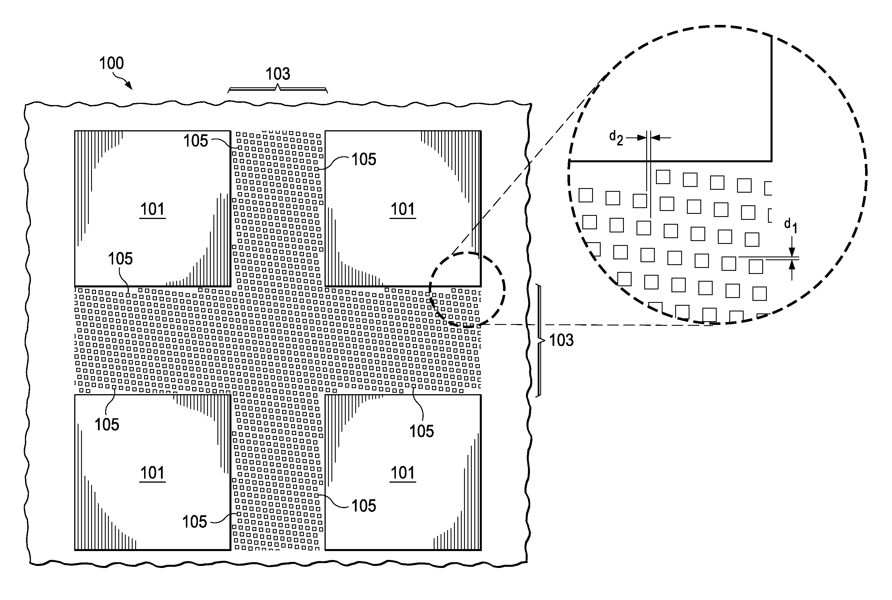
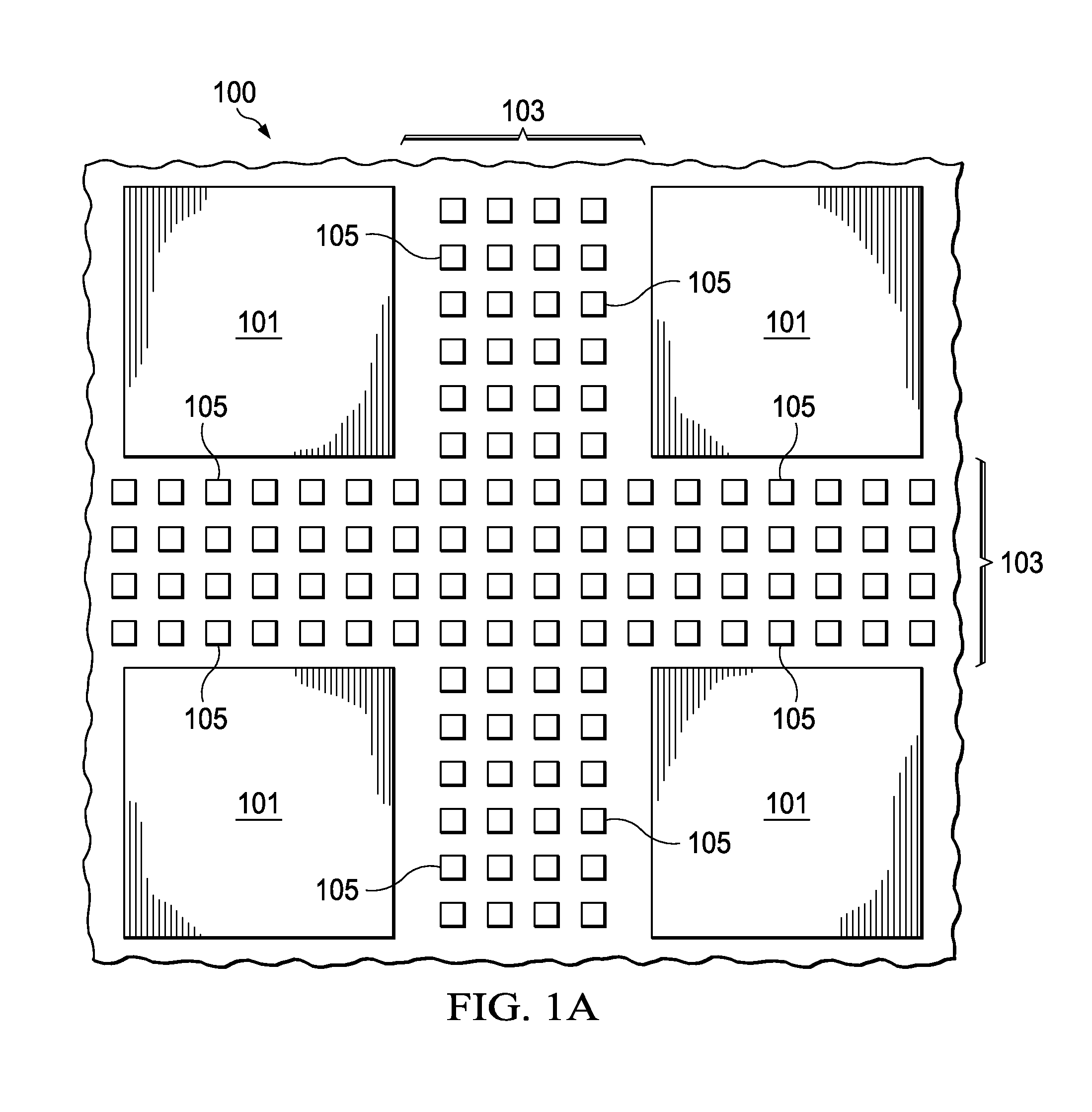
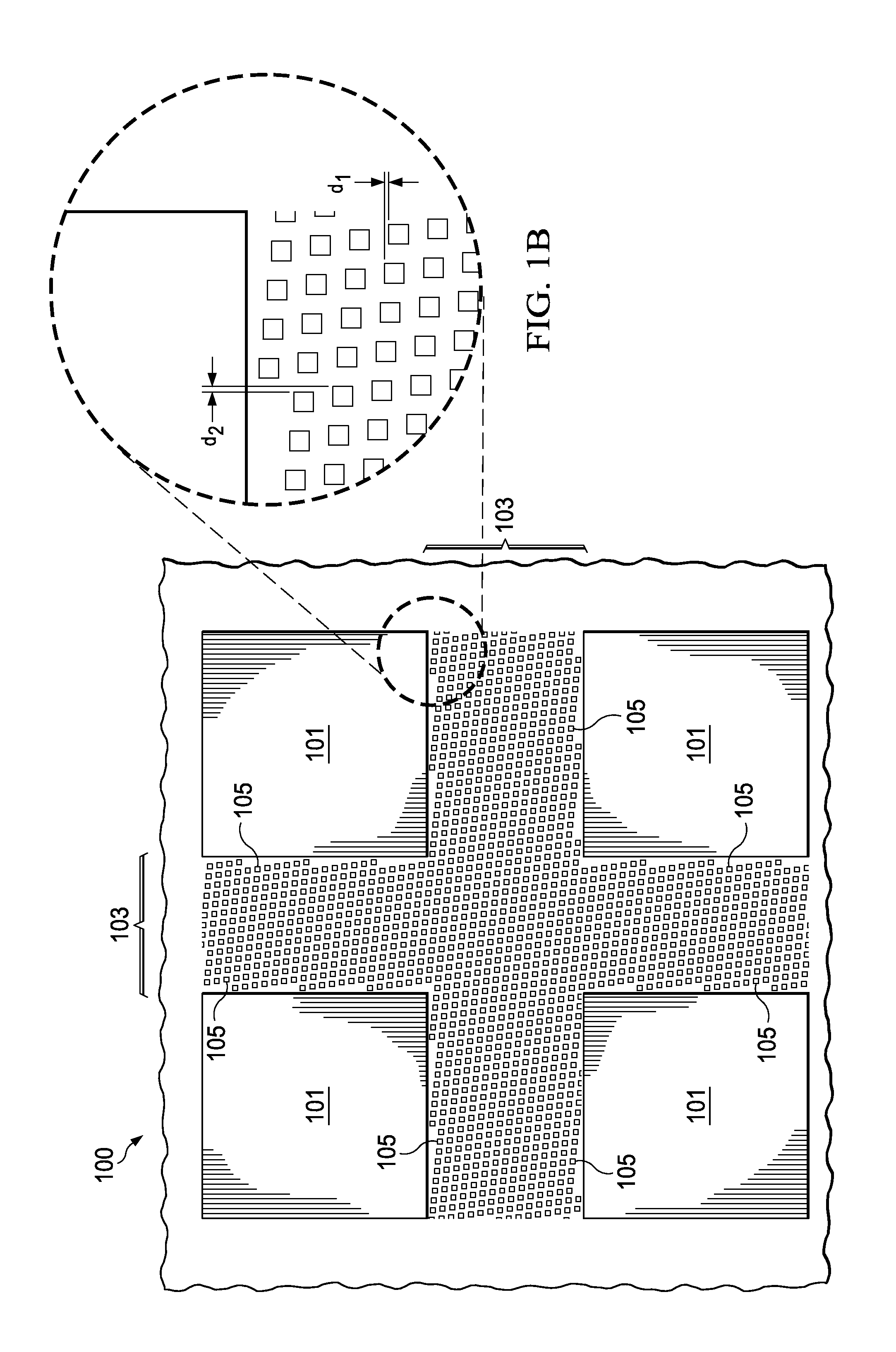
[0020]With reference now to FIG. 1A, there is shown an embodiment of the present invention comprising a plurality of individual dies 101 on a wafer 100, wherein each die 101 includes a substrate (not shown) having electronic devices formed thereon as is known in the art. The substrate is t...


PUM


Abstract

A system and method for preventing defaults during singulation is presented. An embodiment comprises a dummy metal structure located in the scribe region. The dummy metal structure comprises a series of alternating dummy lines that are connected through dummy vias. The dummy lines are offset from dummy lines in adjacent metal layers. Additionally, the dummy lines and dummy vias in the upper layers of the scribe line may be formed with larger dimensions than the dummy lines and dummy vias located in the lower layers.

Description

[0001]This application claims the benefit of U.S. Provisional Patent Application Ser. No. 61 / 153,439, filed on Feb. 18, 2009, and entitled “Scribe Line Metal Structure,” which application is incorporated herein by reference.TECHNICAL FIELD[0002]The present invention relates generally to a system and method for manufacturing semiconductor devices and, more particularly, to improving the quality of dicing when dicing semiconductor dies.BACKGROUND[0003]In the manufacturing of semiconductor devices, integrated circuit dies are formed on a wafer and then separated from the wafer using a saw. Generally, sufficient space is left between adjacent dies to allow for the width of a saw blade during cutting. This space between the dies is referred to as a scribe line, and usually contains test structures used to verify the properties of the die.[0004]Unfortunately, the physical process of sawing the wafer may damage the physical structure of the dies. For example, the saw could crack the silico...

Claims


Application Information

Patent Timeline
Patent Type & Authority Applications(United States)
IPC IPC(8): H01L23/544H01L21/00
CPCH01L21/78
Inventor YU, CHEN-HUAJENG, SHIN-PUUTSAI, HAO-YIHOU, SHANG-YUNCHEN, HSIEN-WEICHIU, MING-YEN
Owner TAIWAN SEMICON MFG CO LTD
Why Eureka
Try Eureka