A compound mold

A composite mold and mold body technology, applied in the field of composite molds, can solve the problems that are not conducive to the control of the dimensional accuracy and surface quality of the blank, affect the dimensional accuracy and surface quality of the blank, increase the grinding amount of the blank product, and meet the requirements of ensuring smoothness , Improve the surface quality, the effect of small deformation

Active Publication Date: 2018-09-18
SANVAC BEIJING MAGNETICS +1
View PDF8 Cites 0 Cited by
  • Summary
  • Abstract
  • Description
  • Claims
  • Application Information

AI Technical Summary

Problems solved by technology

When using traditional non-magnetic steel (such as 1Cr18Ni9Ti, 70Mn, 9Mn9, etc.) The mold cavity is deformed and stuck to powder, which seriously affects the dimensional accuracy and surface quality of the blank, thus increasing the grinding amount of subsequent blank products and greatly increasing the cost
[0005] The patent application of CN20102051339.6 gives a method to improve the uniform orientation field of the cylindrical molding die. By embedding the heat-treated magnetic strip (HRC value is 55) to improve the hardness and the wear resistance of the mold cavity, the mold work is partially improved. The hardness and wear resistance of the region, however, this patent does not essentially solve a series of fundamental problems related to the mold, such as cavity deformation, significantly shortened service life, and significantly reduced compaction accuracy.
CN201010207390.1 patent application provides a molding device for NdFeB materials. The rubber mold containing NdFeB powder is placed in the metal mold and then oriented and pressed. The filling density puts forward very high requirements, and the production efficiency is relatively low; and the service life of the rubber mold is short, and this method is not conducive to controlling the dimensional accuracy and surface quality of the blank

Method used


Image

  • A compound mold
  • A compound mold
  • A compound mold

Examples


Embodiment 1

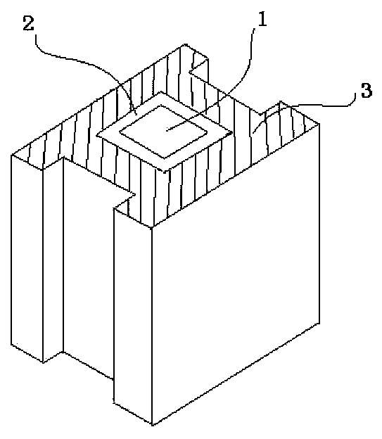
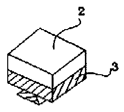
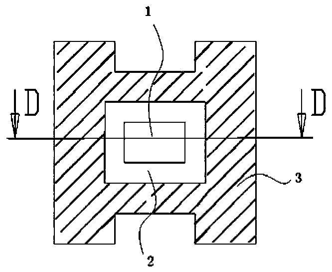
[0035] Figure 2A , 2B , 2C is a structural schematic diagram of a mold for pressing a block-shaped product, as shown in the figure, 1 is a mold cavity, 2 is a graphite material layer, and 3 is a magnetically conductive material layer. The mold body is composed of an outer magnetic material layer and an inner 5mm thick graphite material layer, and the upper and lower indenters are also composed of magnetic material and graphite material, and the thickness of the graphite material layer in contact with the pressed powder is also 5mm. The friction coefficient of the graphite material layer ranges from 0.04 to 0.1, and the thermal expansion coefficient ranges from (0.5 to 3)*10 -6 K -1 , the Mohs intensity value ranges from 1 to 3, and the smoothness value ranges from >0.4. Pour the NdFeB micropowder into the cavity of the mold, then carry out the mold clamping orientation, then the upper and lower block-shaped product pressure heads enter the mold cavity for bidirectional pre...

Embodiment 2

[0041] Figure 3A , 3B , 3C is a structural schematic diagram of a mold for pressing a cylindrical product, as shown in the figure, 1 is a mold cavity, 2 is a graphite material layer, and 3 is a magnetically conductive material layer. The mold body is composed of an outer magnetic material layer and an inner 10mm thick graphite material layer, and the upper and lower indenters are also composed of magnetic material and graphite material, and the thickness of the graphite material layer in contact with the pressed powder is also 10mm. The friction coefficient of the graphite material layer ranges from 0.04 to 0.1, and the thermal expansion coefficient ranges from (0.5 to 3)*10 -6 K -1, the Mohs intensity value ranges from 1 to 3, and the smoothness value ranges from >0.4. Pour the NdFeB micropowder into the cavity of the mold, then carry out the mold clamping orientation, then the upper and lower block-shaped product pressure heads enter the mold cavity for bidirectional pre...

Embodiment 3

[0047] Figure 4A , 4B , 4C is a structural schematic diagram of a mold for pressing trapezoidal products, as shown in the figure, 1 is a mold cavity, 2 is a graphite material layer, and 3 is a magnetically conductive material layer. The mold body is composed of an outer magnetic material layer and an inner 30mm thick graphite material layer, and the upper and lower indenters are also composed of magnetic material and graphite material, and the thickness of the graphite material layer in contact with the pressed powder is also 30mm. The friction coefficient of the graphite material layer ranges from 0.04 to 0.1, and the thermal expansion coefficient ranges from (0.5 to 3)*10 -6 K -1 , the Mohs intensity value ranges from 1 to 3, and the smoothness value ranges from >0.4. Pour the NdFeB micropowder into the cavity of the mold, then carry out the mold clamping orientation, then the upper and lower block-shaped product pressure heads enter the mold cavity for bidirectional pre...


PUM

PropertyMeasurementUnit
thicknessaaaaaaaaaa
friction coefficientaaaaaaaaaa

Abstract

The invention discloses a combined mold which comprises a mold body, an upper pressing head and a lower pressing head, and is characterized in that the mold body adopts an integrated structure; the inner sides and the outer sides of the mold body, the upper pressing head and the lower pressing head are made of different materials; particularly, the outer sides of the mold body, the upper pressing head and the lower pressing head are made of a magnetism-conductive material, and the inner sides of the mold body, the upper pressing head and the lower pressing head are made of a graphite material. Due to the adoption of high-intensity graphite, the service life of the mold is obviously prolonged, and the forming qualification rate of a permanent magnet material blank product can be increased; the surface precision and the smoothness requirement of the blank product are improved, and the pressing cost is lowered.

Description

technical field [0001] The invention relates to a composite mold, in particular to a composite mold used in the compression molding process of permanent magnet materials. Background technique [0002] In the production process of permanent magnet materials produced by powder metallurgy process, it generally includes powder making-pressing-sintering and other processes. In order to obtain the permanent magnetism of the product, it is necessary to put the micro powder in the mold and press the magnetic field orientation to obtain a compact product. In this process, the molding die has an important influence on the molding quality of the compact product and the magnetic properties of the final magnet. [0003] At present, the vertical magnetic field orientation molding press is generally used, that is, the orientation direction of the magnetic field is perpendicular to the pressing direction. The electromagnet is fixed on the operating platform of the press, and the two sets of...

Claims


Application Information

Patent Timeline
Patent Type & Authority Patents(China)
IPC IPC(8): B22F3/03
Inventor 陈国安张瑾赵玉刚刘长庆裴仁鹏
Owner SANVAC BEIJING MAGNETICS
Why Eureka
Try Eureka