Robust Location Distinction Using Temporal Link Signatures

a temporal link and location distinction technology, applied in the field of wireless networks, can solve the problems of ineffective unable to achieve and unable to achieve the effect of efficient and robust use of existing techniques

Active Publication Date: 2010-08-19
UNIV OF UTAH RES FOUND
View PDF57 Cites 19 Cited by
  • Summary
  • Abstract
  • Description
  • Claims
  • Application Information

AI Technical Summary

Problems solved by technology

In particular, wireless networks can be vulnerable to medium access control (MAC) address spoofing.
Traditional cryptography methods can be implemented to prevent this spoofing; however, these methods are susceptible to node compromise.
However, existing techniques fail to do so in an efficient and robust manner.
However, accelerometers can be cost prohibitive.
The additional device cost of an accelerometer may be acceptable for protection of high-value assets, but would be prohibitive for applications such as bar-code replacement and large-scale sensor networks.
Furthermore, an accelerometer needs continuous power that would excessively drain battery power since the accelerometer cannot detect motion from a sleep state.
However, the use of Doppler measurements is limited to situations only in which the object is moving.
That is, Doppler measurements provide limited information after object has stopped moving.
Thus, transmission of a Doppler signal could not be intermittent like a packet radio, and would require excessive use of battery power.
However, RSS measurements vary due to small-scale and frequency-selective fading, such that its use in location distinction requires multiple measurements at different receivers.
However, for wireless sensor networks, multi-node collaboration is expensive in terms of energy requirements and usage.

Method used


Image

  • Robust Location Distinction Using Temporal Link Signatures
  • Robust Location Distinction Using Temporal Link Signatures
  • Robust Location Distinction Using Temporal Link Signatures

Examples


Embodiment Construction

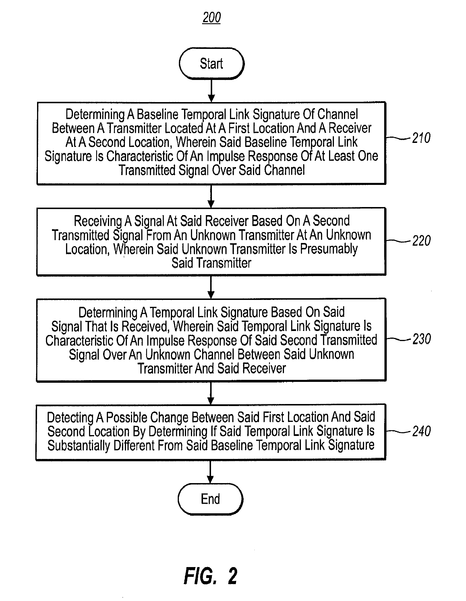
[0022]Reference will now be made in detail to the preferred embodiments of the present invention, a method and system for performing location distinction in a wireless network for purposes of detecting a change in transmitter or receiver location, or a combination of both. While the invention will be described in conjunction with the preferred embodiments, it will be understood that they are not intended to limit the invention to these embodiments. On the contrary, the invention is intended to cover alternatives, modifications and equivalents which may be included within the spirit and scope of the invention as defined by the appended claims.

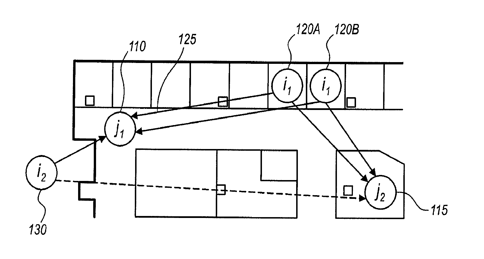
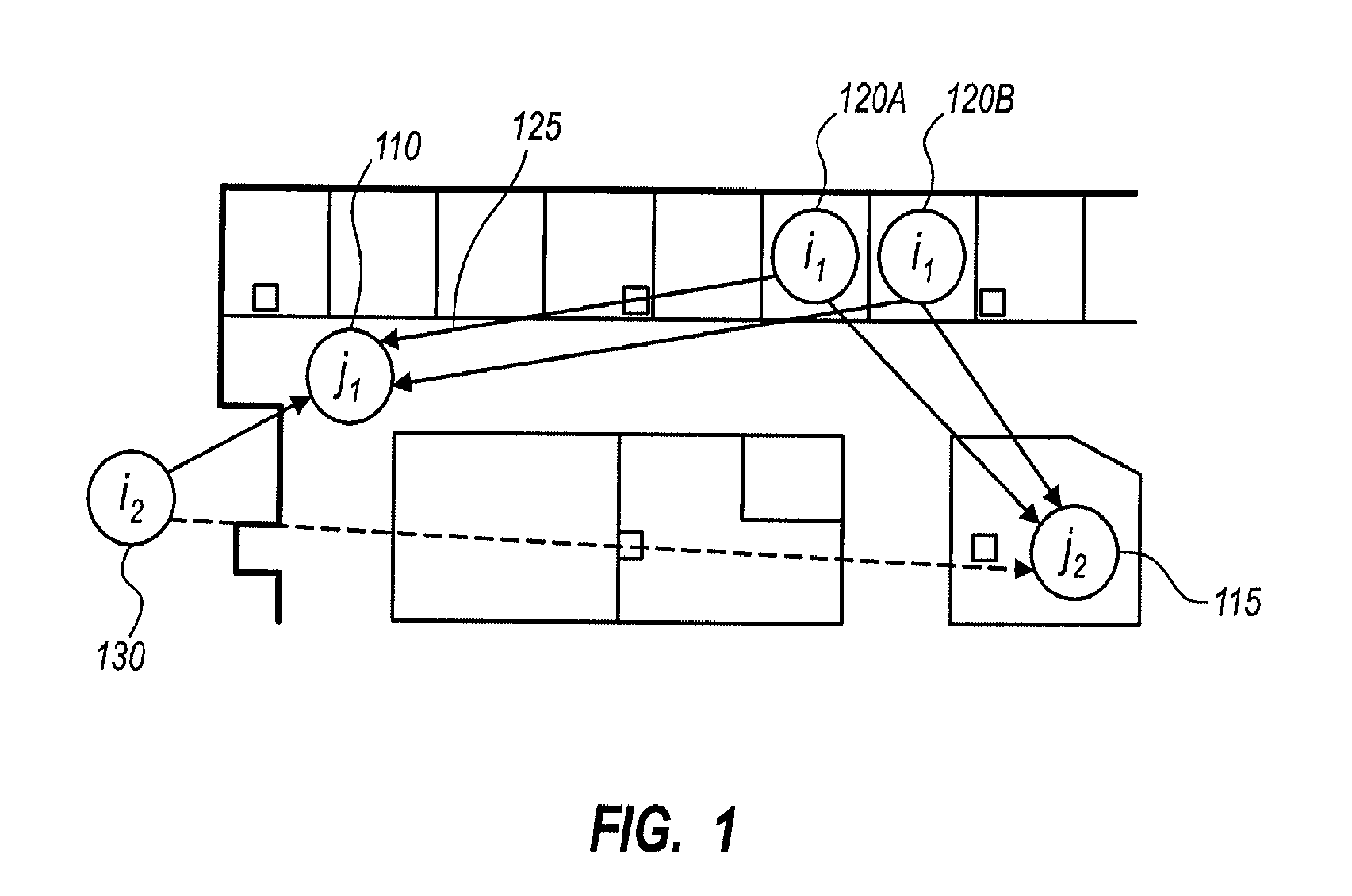
[0023]Accordingly, embodiments of the present invention provide for a robust location distinction mechanism that uses a physical layer characteristic of the radio channel between a transmitter and a receiver, that comprises a temporal link signature. The temporal link signature is the sum of the effects of the multiple paths from the transmitter...


PUM


Abstract

The ability of a receiver to determine when a transmitter has changed location is important for energy conservation in wireless sensor networks, for physical security of radio tagged objects, and for wireless network security in detection of replication attacks. In embodiments of the present invention, a measured temporal link signature is determined to uniquely identify the link between a transmitter and a receiver. The temporal link signature is an impulse response of a transmitted signal from the transmitter over a channel between the transmitter and a receiver over a channel. When the transmitter changes location, or if an attacker at a different location assumes the identity of the transmitter, the proposed link distinction methodology reliably detects the change in the physical channel. This detection can be performed at a single receiver or collaboratively by multiple receivers.

Description

CROSS-REFERENCE TO RELATED APPLICATIONS[0001]The present invention claims priority to and the benefit of Provisional Application No. 60 / 970,094 to Patwari et al., entitled “Robust Location Distinction Using Temporal Link Signatures,” filed on Sep. 5, 2007, which is herein incorporated by reference in its entirety.FIELD OF INVENTION[0002]The present invention relates to the field of wireless networks. Specifically, the present invention relates to a temporal link signature that uniquely identifies the link between a transmitter and a receiver.THE RELEVANT TECHNOLOGY[0003]Location distinction is critical in many wireless network situations, including motion detection in wireless sensor networks, physical security of objects using wireless tags, and information security against replication attacks. Some applications requiring location distinction and motion detection include wireless sensor networks, active radio frequency identification (RFID), and secure wireless networks.[0004]For i...

Claims


Application Information

Patent Timeline
Patent Type & Authority Applications(United States)
IPC IPC(8): G06K7/01
CPCG01S5/0252H04L63/1466H04W84/18H04W64/00H04W12/12Y02D30/70H04W12/122H04W12/126
Inventor PATWARI, NEALKASERA, SNEHA
Owner UNIV OF UTAH RES FOUND
Why Eureka
Try Eureka