Touch panel and method of detecting press operation position thereon

a technology of press operation and touch panel, which is applied in the field of touch panel, can solve the problems of complicated connection to electronic circuit and arithmetic processing for detecting position, long time for detecting position, etc., and achieve the effect of preventing the increase of the entire outer shape, and reducing the number of electrodes

Inactive Publication Date: 2010-08-19
PANASONIC CORP
View PDF5 Cites 41 Cited by
  • Summary
  • Abstract
  • Description
  • Claims
  • Application Information

AI Technical Summary

Benefits of technology

[0015]That is to say, only by detecting a voltage on the belt-shaped conductive layer, the pressed position can be detected. Moreover, even when a plurality of places are pressed, each of the pressed positions can be detected in a case the pressed positions correspond to different belt-shaped conductive layers. Furthermore, the number of electrodes can be reduced, thus preventing the entire outer shape from being increased. At the same time, connection to an electronic circuit and arithmetic processing for detecting positions can be simplified.

Problems solved by technology

Moreover, since it is necessary to detect a pressed position by sequentially applying a voltage to all of the electrodes, it takes a long time to detect a position.
The connection to an electronic circuit and arithmetic processing for detecting a position become complicated.

Method used


Image

  • Touch panel and method of detecting press operation position thereon
  • Touch panel and method of detecting press operation position thereon
  • Touch panel and method of detecting press operation position thereon

Examples


first exemplary embodiment

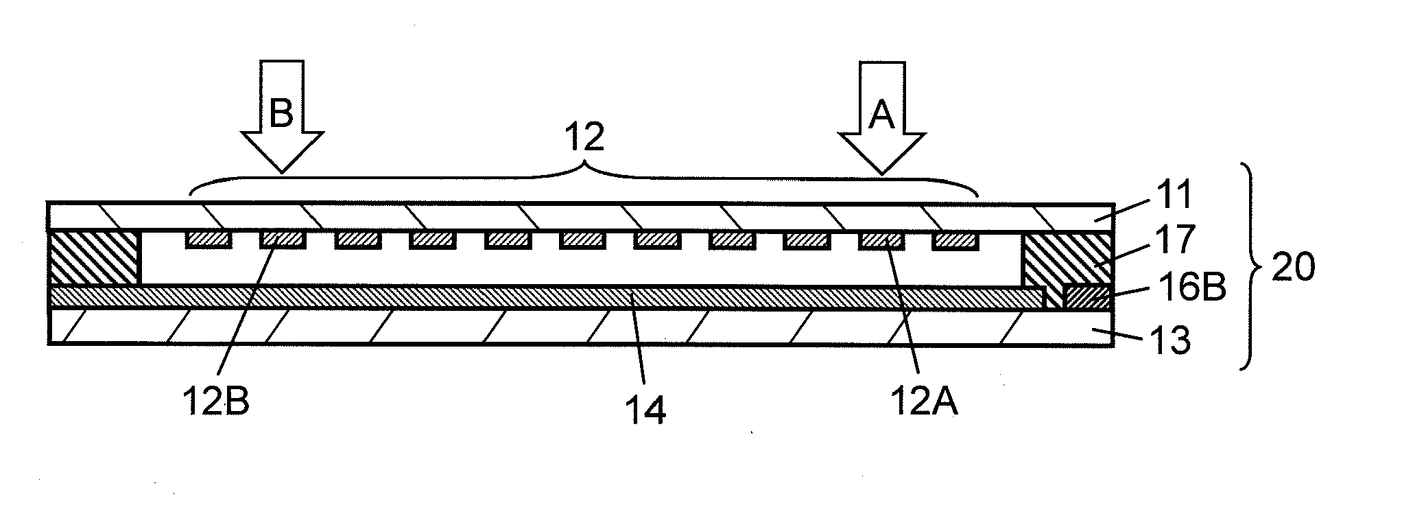
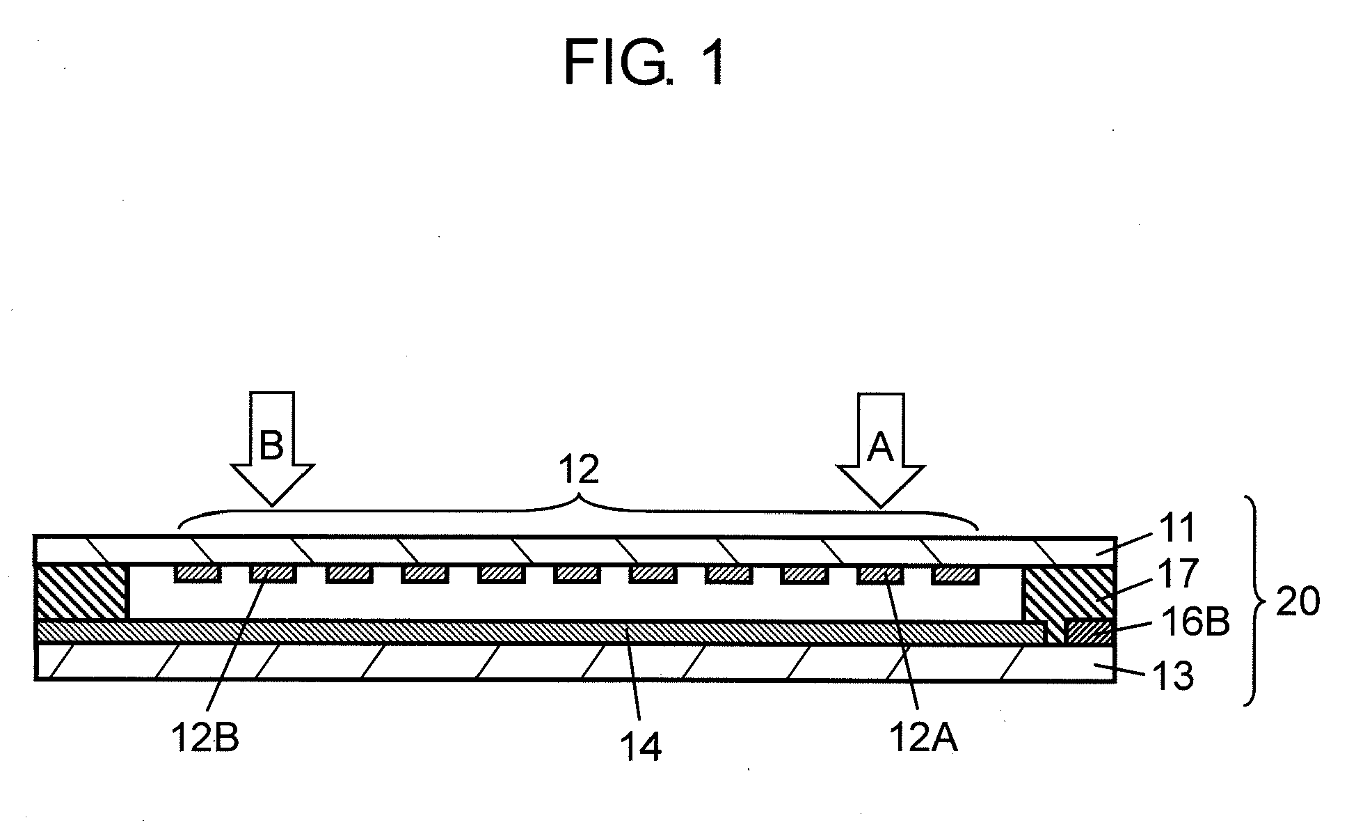
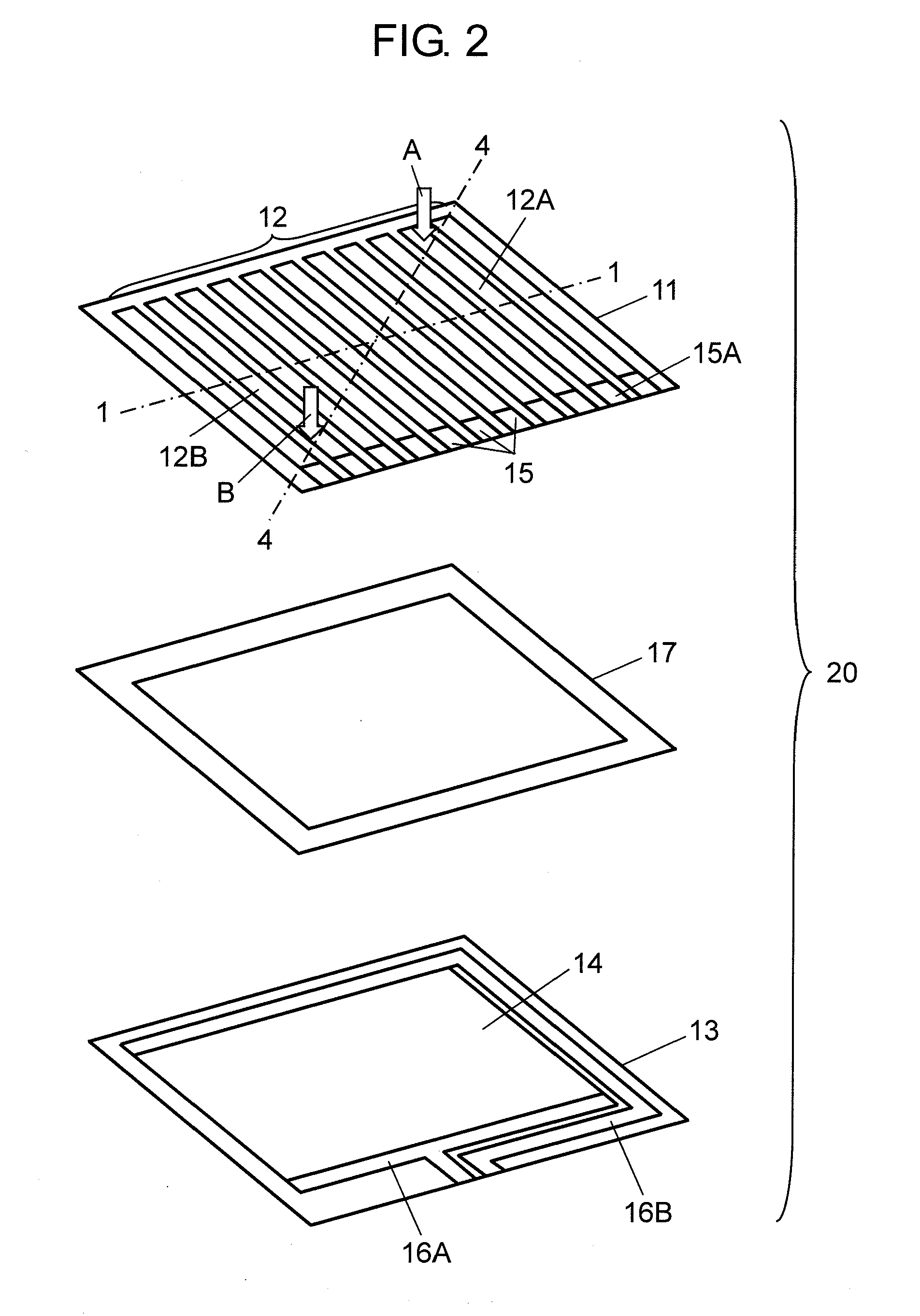
[0037]FIGS. 1 and 2 are a sectional view and an exploded perspective view of a touch panel in accordance with a first embodiment of the present invention. FIG. 1 shows a cross section taken on line 1-1 shown in FIG. 2. FIG. 3 is a diagram showing a connection between the touch panel and an electronic circuit. FIG. 4 is a conceptual view in a cross section taken on line 4-4 in FIG. 2. Touch panel 20 includes upper substrate 11, lower substrate 13 and spacer 17.

[0038]Light-transparent upper substrate 11 is made of light-transparent resin such as polyethylene terephthalate, polyether sulphone, and polycarbonate. Light transparent upper conductive layer 12 made of indium tin oxide, oxide tin, or the like, is formed on the bottom surface of upper substrate 11 by sputtering or the like. Upper conductive layer 12 is formed of belt-shaped conductive layers 12A, 12B and the other belt-shaped conductive layers, each formed in a width of about 0.3-2 mm with an interval of about 0.6-4 mm. On th...

second exemplary embodiment

[0064]FIGS. 11 and 12 are a sectional view and an exploded perspective view showing a touch panel in accordance with a second embodiment of the present invention. FIG. 13 is a diagram showing a connection between the touch panel and an electronic circuit. Touch panel 130 includes upper substrate 111, a plurality of belt-shaped upper conductive layers 112, upper resistive layer 113, first upper electrode 117A, second upper electrode 117B, lower substrate 114, a plurality of belt-shaped lower conductive layers 115, lower resistive layer 116, first lower electrode 118A, second lower electrode 118B, and spacer 119.

[0065]Light-transparent upper substrate 111 is made of polyethylene terephthalate, polyether sulphone, or polycarbonate. Belt-shaped upper conductive layers 112 are formed on the bottom surface of upper substrate 111. Upper conductive layers 112 are made of indium tin oxide, oxide tin, or the like, and formed in the front-rear direction by sputtering or the like. Upper resisti...


PUM


Abstract

In a touch panel, one of conductive layers on a bottom of an upper substrate and on a top of a lower substrate is formed of belt-shaped conductive layers. The other is a single conductive layer facing the belt-shaped conductive layers. The single conductive layer is provided with a pair of electrodes in positions corresponding to both ends in a direction where the belt-shaped conductive layers extend. When the upper substrate is pressed while a voltage is applied between the pair of electrodes, the top and lower conductive layers contact with each other. Then, a voltage value corresponding to the pressed position in the direction where the belt-shaped conductive layers extend is generated from any of the belt-shaped conductive layers. From the voltage value and the position of the belt-shaped conductive layer from which the voltage value is generated, a pressed position on the upper substrate can be detected.

Description

BACKGROUND OF THE INVENTION[0001]1. Field of the Invention[0002]The present invention relates to a touch panel mainly used for operating various kinds of electronic equipments and a method of detecting a press operation position thereon.[0003]2. Background Art[0004]Recently, various kinds of electronic equipments such as a portable telephone and an electronic camera have advanced in functions and become diversified. Along with this, the number of equipments in which a light-transparent touch panel is mounted on the front surface of a liquid crystal display device or the like is increasing. A user operates by pressing a touch panel with a finger thereof, a pen, or the like, while viewing the indication on a display device at the back of the touch panel. According to this operation, various functions of equipment can be switched from one function to another. Such a conventional touch panel is described with reference to FIG. 19. FIG. 19 is a sectional view showing a conventional touch...

Claims


Application Information

Patent Timeline
Patent Type & Authority Applications(United States)
IPC IPC(8): G06F3/045
CPCG06F3/045
Inventor TANABE, KOJIWATANABE, HIROTOSHIHIRAOKA, HIDETOSHIMATSUMOTO, KENICHI
Owner PANASONIC CORP
Why Eureka
Try Eureka