
Fusion of a 2d electro-optical image and 3D point cloud data for scene interpretation and registration performance assessment

a technology of electro-optical image and applied in image analysis, instruments, computing, etc., can solve the problems of difficult interpretation of 3d point cloud data, difficult 2d to 3d image registration step, time-consuming, etc., and achieve the effect of improving the visualization of a common scen

Active Publication Date: 2010-08-19
HARRIS CORP
View PDF48 Cites 99 Cited by
  • Summary
  • Abstract
  • Description
  • Claims
  • Application Information

AI Technical Summary

Problems solved by technology

Point-cloud data can be difficult to interpret because the objects or terrain features in raw data are not easily distinguishable.
Notwithstanding the use of such conventional color maps, 3D point cloud data has remained difficult to interpret.
The 2D to 3D image registration step can be difficult and time consuming because it requires precise alignment of the EO and LIDAR data acquired by different sensors at different data collection times and different relative sensor positions.
Moreover, the point cloud data is usually a different format as compared to the EO image data, making for a more complex registration problem.
However, visual interpretation of the resulting registered EO and LIDAR data often remains difficult for human analysts.
This creates two noteworthy problems.
In particular, it makes it more difficult for a person to visualize the scene being represented by the fused image data.
This occurs because it is can be difficult to comprehend how the point cloud data fits into the two-dimensional image.
The same effect also makes it more difficult to evaluate how well the registration process has worked.
With the three-dimensional point cloud data appearing to float above a flat two-dimensional surface, it is difficult for a human to judge how well the various features represented by the point cloud (e.g. structures, vehicles) align with corresponding features in the two-dimensional image (e.g. building outlines or footprints, and roads).

Method used


Image

  • Fusion of a 2d electro-optical image and 3D point cloud data for scene interpretation and registration performance assessment
  • Fusion of a 2d electro-optical image and 3D point cloud data for scene interpretation and registration performance assessment
  • Fusion of a 2d electro-optical image and 3D point cloud data for scene interpretation and registration performance assessment

Examples


Embodiment Construction

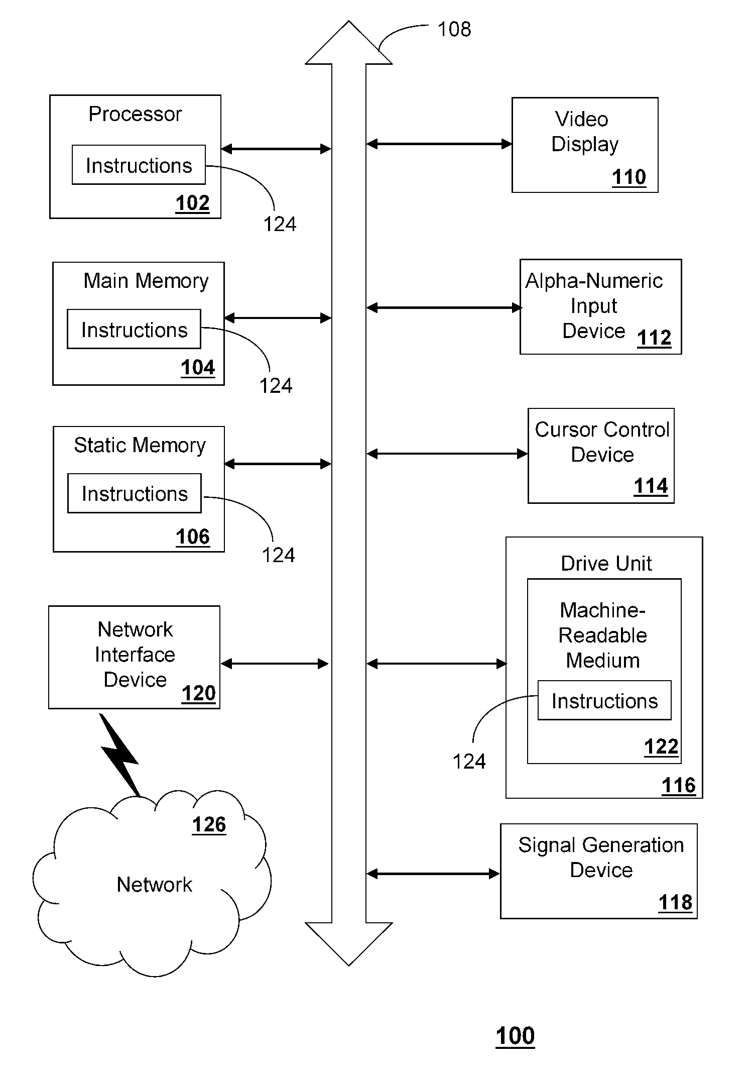
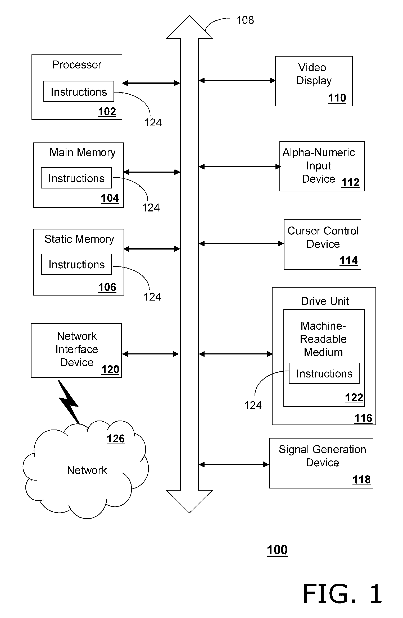
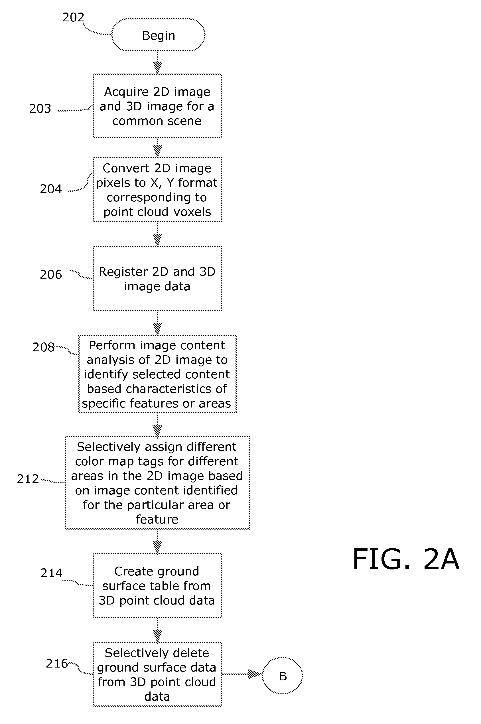
[0021]In the present invention, a 2D image is modified and then fused with 3D point cloud data for a common scene. The process facilitates analysis of the scene and permits improved evaluation of the quality of the image registration process. The 2D image and 3D point cloud data are registered utilizing a suitable registration process. Thereafter, the 3D point cloud data is processed to identify and define a ground table. The ground table represents a contour of the ground in the scene. The ground table is then used to transform the 2D image into a virtual 3D image comprising a ground surface contour. The virtual 3D image is created by selectively modifying a Z value associated with the pixels of the 2D image so that they generally conform to the Z values defined by the ground table. In this way, the contours of the ground surface are imparted to the 2D image, thereby forming the virtual 3D image. Once this process is complete, the previously registered 3D point cloud data is overla...


PUM


Abstract

Method and system for combining a 2D image with a 3D point cloud for improved visualization of a common scene as well as interpretation of the success of the registration process. The resulting fused data contains the combined information from the original 3D point cloud and the information from the 2D image. The original 3D point cloud data is color coded in accordance with a color map tagging process. By fusing data from different sensors, the resulting scene has several useful attributes relating to battle space awareness, target identification, change detection within a rendered scene, and determination of registration success.

Description

BACKGROUND OF THE INVENTION[0001]1. Statement of the Technical Field[0002]The inventive arrangements concern registration of two-dimensional and three dimensional image data, and more particularly methods for visual interpretation of registration performance of 2D and 3D image data. This technique is used as a metric to determine registration success.[0003]2. Description of the Related Art[0004]Conventional electro-optical (EO) sensors have long been used for collection of such image data and generally produce two dimensional data. Such data generally corresponds to a projection of the image onto a planar field which can be entirely defined by an x and y coordinate axis. More recently, there has been a growing interest in three-dimensional imaging data. For example, LIDAR systems use a high-energy laser, optical detector, and timing circuitry to generate three-dimensional point cloud data. Each point in the 3D point cloud is spatially analogous to the pixel data generated by a digit...

Claims


Application Information

Patent Timeline
Patent Type & Authority Applications(United States)
IPC IPC(8): G06T15/00
CPCG06T7/0024G06T7/30G06T7/00G06T15/00
Inventor MINEAR, KATHLEENPOOLEY, DONALDSMITH, ANTHONY O'NEIL
Owner HARRIS CORP
Learn More