
Image recording apparatus, image processing apparatus and image processing method and computer-readable medium

Active Publication Date: 2010-08-19
FUJIFILM CORP
View PDF3 Cites 30 Cited by
  • Summary
  • Abstract
  • Description
  • Claims
  • Application Information

AI Technical Summary

Benefits of technology

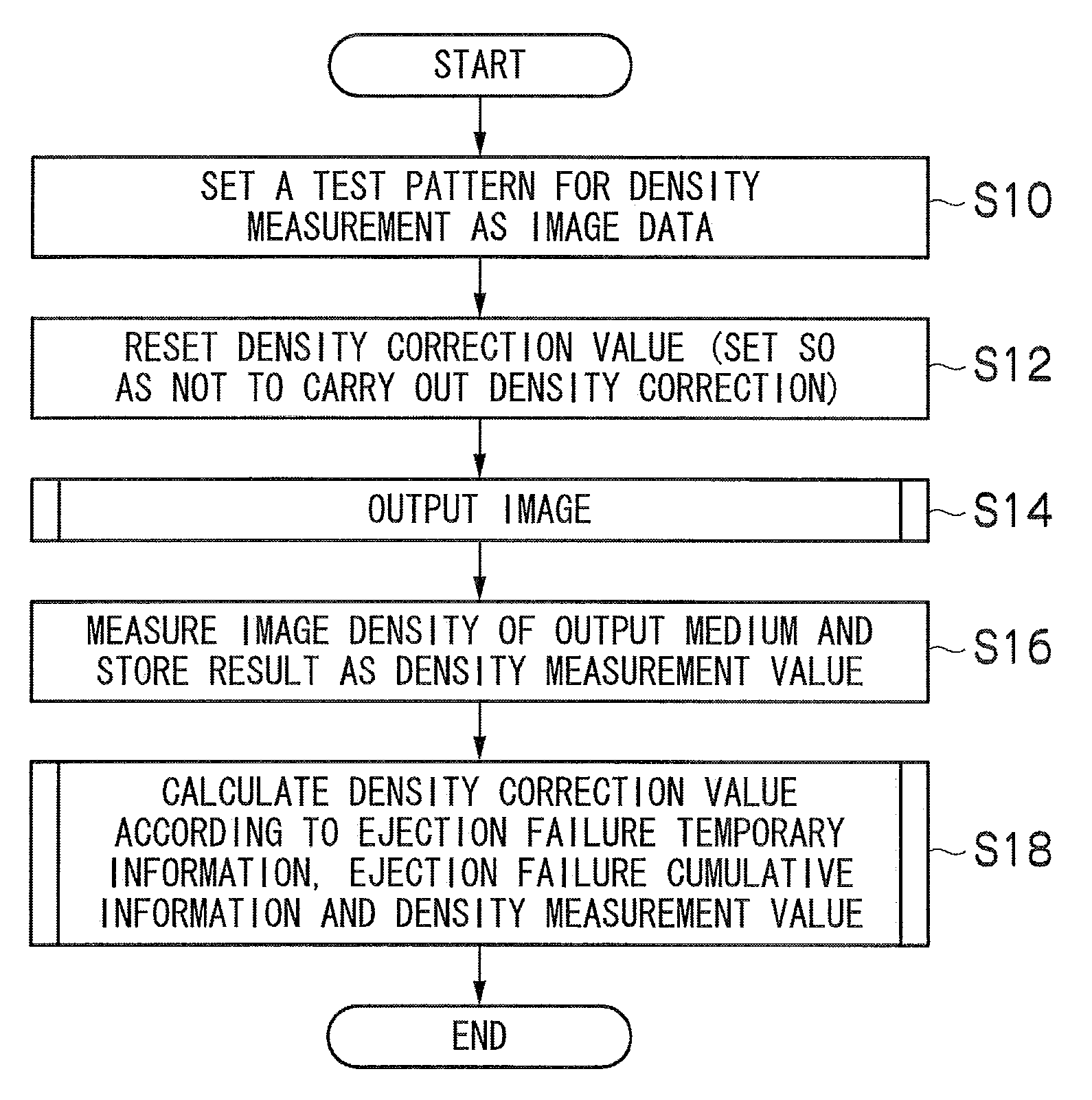
[0009]The present invention has been contrived in view of these circumstances, an object thereof being to provide an image recording apparatus, an image processing apparatus, an image processing method and a computer-readable medium whereby image processing can be carried out appropriately even in cases where ejection failure correction and density correction are used conjointly, without over-correction due to duplication of the ejection failure correction and the density correction.

Problems solved by technology

In the technology described in Japanese Patent Application Publication No. 2003-136764, if an inexpensive scanner having low resolution is used, then the density of the portion of the ejection failure nozzle affects the measured density of the neighboring nozzles, and ejection failure correction and shading correction (density correction) are not carried out correctly.
However, with the technology described in Japanese Patent Application Publication No. 2003-136764, it takes time to calculate the correction values.
Moreover, in a case where ejection failure correction is carried out by using ink of a different color, there are possibilities that the types of inks of different colors are restricted, for instance, only C, M and Y inks in the case of K ink, and the color tone is changed by the correction process.
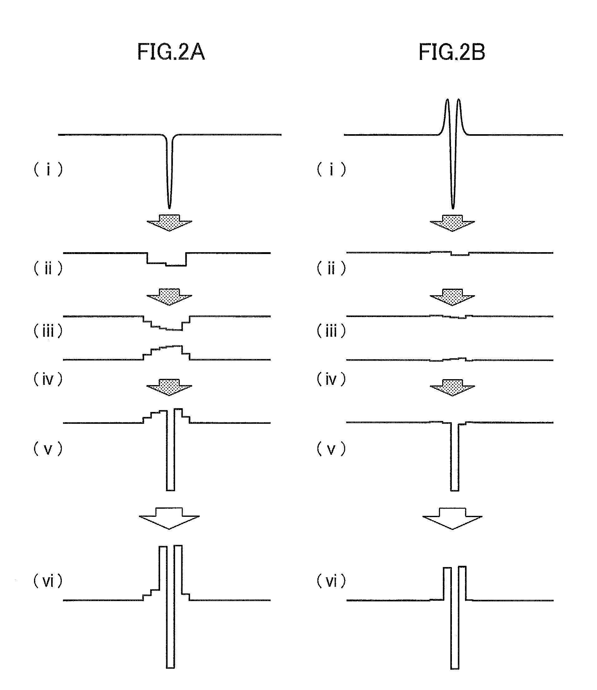
However, if this density correction is carried out in conjunction with the ejection failure correction described above, then the ejection failure correction and the density correction are duplicated, and over-correction may occur.

Method used


Image

  • Image recording apparatus, image processing apparatus and image processing method and computer-readable medium
  • Image recording apparatus, image processing apparatus and image processing method and computer-readable medium
  • Image recording apparatus, image processing apparatus and image processing method and computer-readable medium

Examples


Embodiment Construction

[0059]Below, preferred embodiments of the present invention are described in detail in accordance with the accompanying drawings.

Occurrence of Over-Correction Due to Duplication of Ejection Failure Correction and Density Correction

[0060]Firstly, the occurrence of over-correction due to duplication of ejection failure correction and density correction will be described.

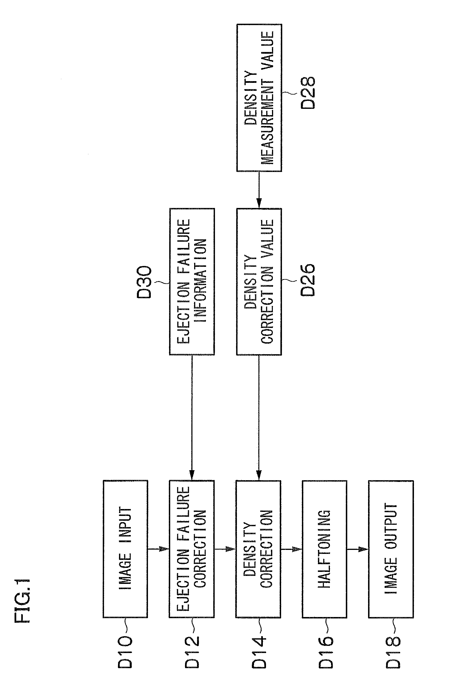
[0061]FIG. 1 is a diagram illustrating the flow of data relating to ejection failure correction and density correction according to the related art.

[0062]Ejection failure information (D30) relating to an ejection failure nozzle (non-ejection nozzle) is acquired by ejection failure determination (non-ejection determination). This ejection failure information (D30) is acquired from a test chart for ejection failure determination which is printed in the margin area, for example, each time an image is output. The details of the test chart for ejection failure determination are described hereinafter.

[0063]Furthermore, in th...


PUM


Abstract

An image recording apparatus includes: a recording head having a plurality of recording elements; a conveyance device which conveys at least one of the recording head and a recording medium so as to cause relative movement between the recording head and the recording medium; a recording defect information acquisition device which acquires recording defect information indicating a recording element having a recording defect, of the plurality of recording elements; a recording defect correction device which corrects an image defect caused by the recording element having a recording defect, according to the recording defect information acquired by the recording defect information acquisition device; an image reading apparatus which reads in an image of a test chart for density measurement recorded by the recording head, the image of the test chart for density measurement having been corrected by the recording defect correction device; a recording density information acquisition device which acquires recording density information indicating recording density of the plurality of recording elements, according to the image of the test chart for density measurement read in by the image reading apparatus; a density correction information calculation device which calculates density correction information according to the recording density information acquired by the recording density information acquisition device; a density correction device which corrects density of image data according to the density correction information calculated by the density correction information calculation device; an uncorrected recording defect information acquisition device which acquires uncorrected recording defect information indicating a recording element having a new recording defect which has not been corrected by the recording defect correction device when the test chart for density measurement is output; and a recording density information amendment device which amends the density correction information according to the uncorrected recording defect information acquired by the uncorrected recording defect information acquisition device.

Description

BACKGROUND OF THE INVENTION[0001]1. Field of the Invention[0002]The present invention relates to an image recording apparatus, an image processing apparatus, an image processing method and a computer-readable medium, and more particularly, to an image recording apparatus, an image processing apparatus, an image processing method and a computer-readable medium which correct density non-uniformities caused by variations in the characteristics with respect to each of recording elements when an image is recorded on a recording medium (recording paper) using a recording head in which a plurality of recording elements are provided.[0003]2. Description of the Related Art[0004]Japanese Patent Application Publication No. 2003-136764 discloses an inkjet recording apparatus which records an image by ejecting ink onto a recording medium using a recording head in which a plurality of nozzles for ejecting ink are arranged, wherein a pattern for measuring the recording characteristics of the recor...

Claims


Application Information

Patent Timeline
IPC IPC(8): B41J29/38B41J29/393
CPCB41J29/393
Inventor SASAYAMA, HIROYUKI
Owner FUJIFILM CORP
Learn More