
Camera body and imaging device

a camera body and imaging device technology, applied in the field of imaging devices, can solve the problems of difficult to tell which way the zoom lever should be operated, and it is still difficult for users to confirm the relationship between, increase or decrease the distance of objects, and achieve the effect of convenient operation

Active Publication Date: 2010-08-19
PANASONIC INTELLECTUAL PROPERTY MANAGEMENT CO LTD
View PDF33 Cites 86 Cited by
  • Summary
  • Abstract
  • Description
  • Claims
  • Application Information

AI Technical Summary

Benefits of technology

[0015]It is an object of the present invention to provide a camera body and an imaging device with which operation is easier.
[0017]With this camera body, the display unit is controlled by the control unit so that the direction in which the operation member moves substantially coincides with a change direction in which the state indicator displayed on the display unit changes according to the operation of the operation member. Accordingly, if the user captures an image while looking at the state indicator displayed on the display unit, the user can intuitively tell which way to operate the operation member in adjusting the state of the optical system. Consequently, this camera body is easier to operate. Also, the same effect can be obtained with an imaging device having this camera body.

Problems solved by technology

However, with the digital camera discussed in Patent Citation 2, although the direction in which the zoom lever is operated and the zoom position are displayed on a display unit, the display of the operation direction is not correlated to the operation direction of the zoom lever, so even if the user looks at the display of the zoom position, it is hard to tell which way the zoom lever should be operated.
Also, with the digital camera discussed in Patent Citation 3, this merely allows the operation direction of the focus ring to be selected as desired, and it is still hard for the user to confirm the relationship between the operation direction of the focus ring and the increase or decrease in the object distance.
As explained above, with a conventional imaging device, there is a need for easier operation since it is hard for the user to confirm which way to operate the controls in changing the state of the optical system.

Method used


Image

  • Camera body and imaging device
  • Camera body and imaging device
  • Camera body and imaging device

Examples


first embodiment

1: Overall Configuration of Digital Camera

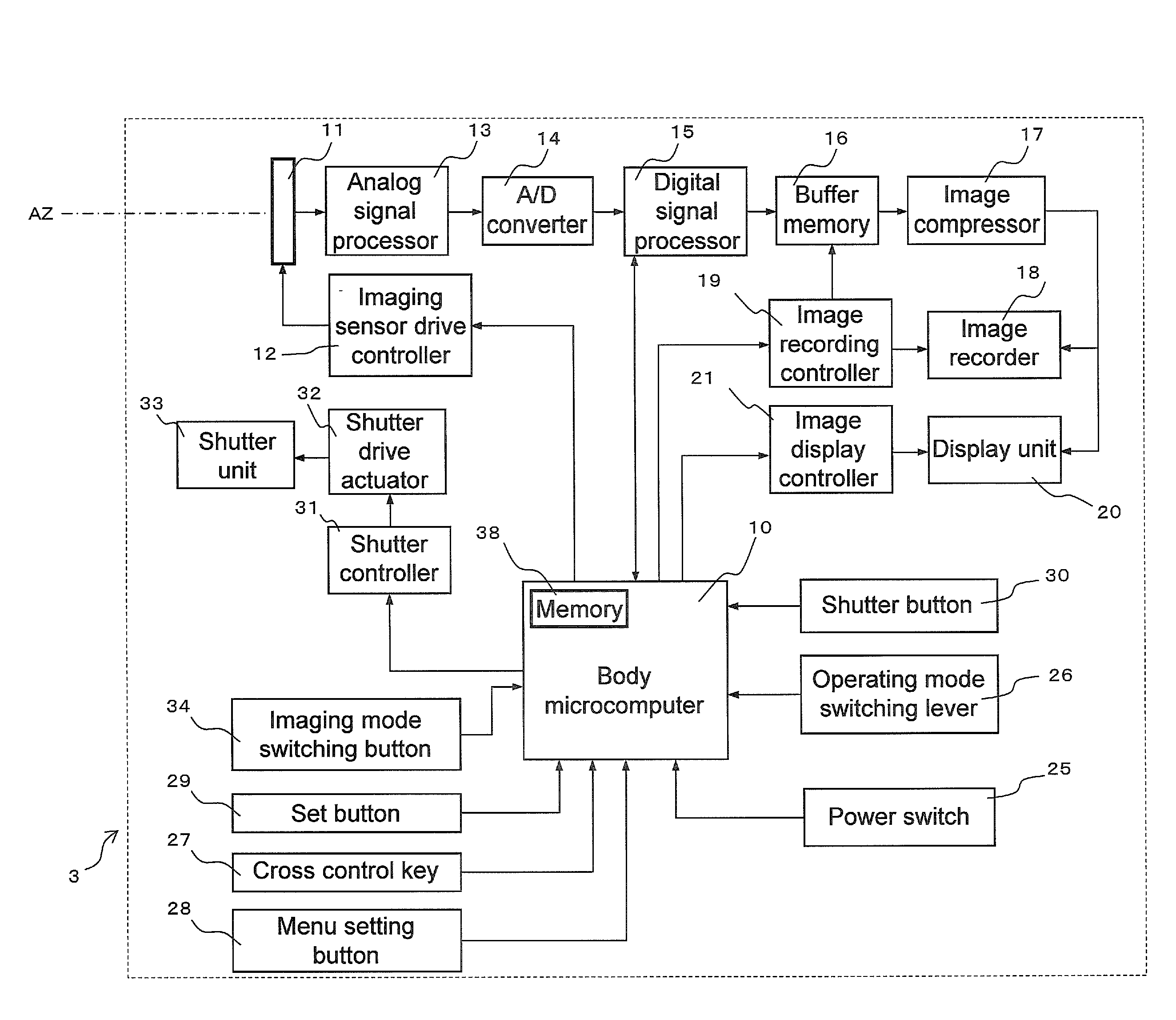
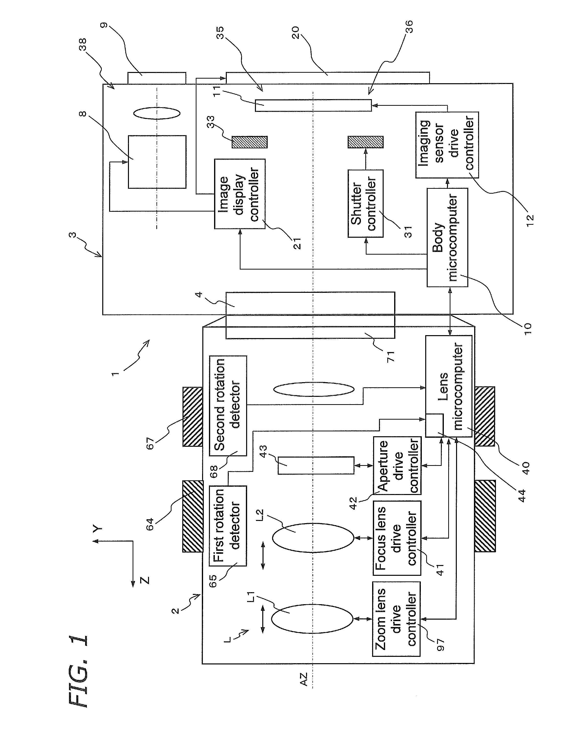
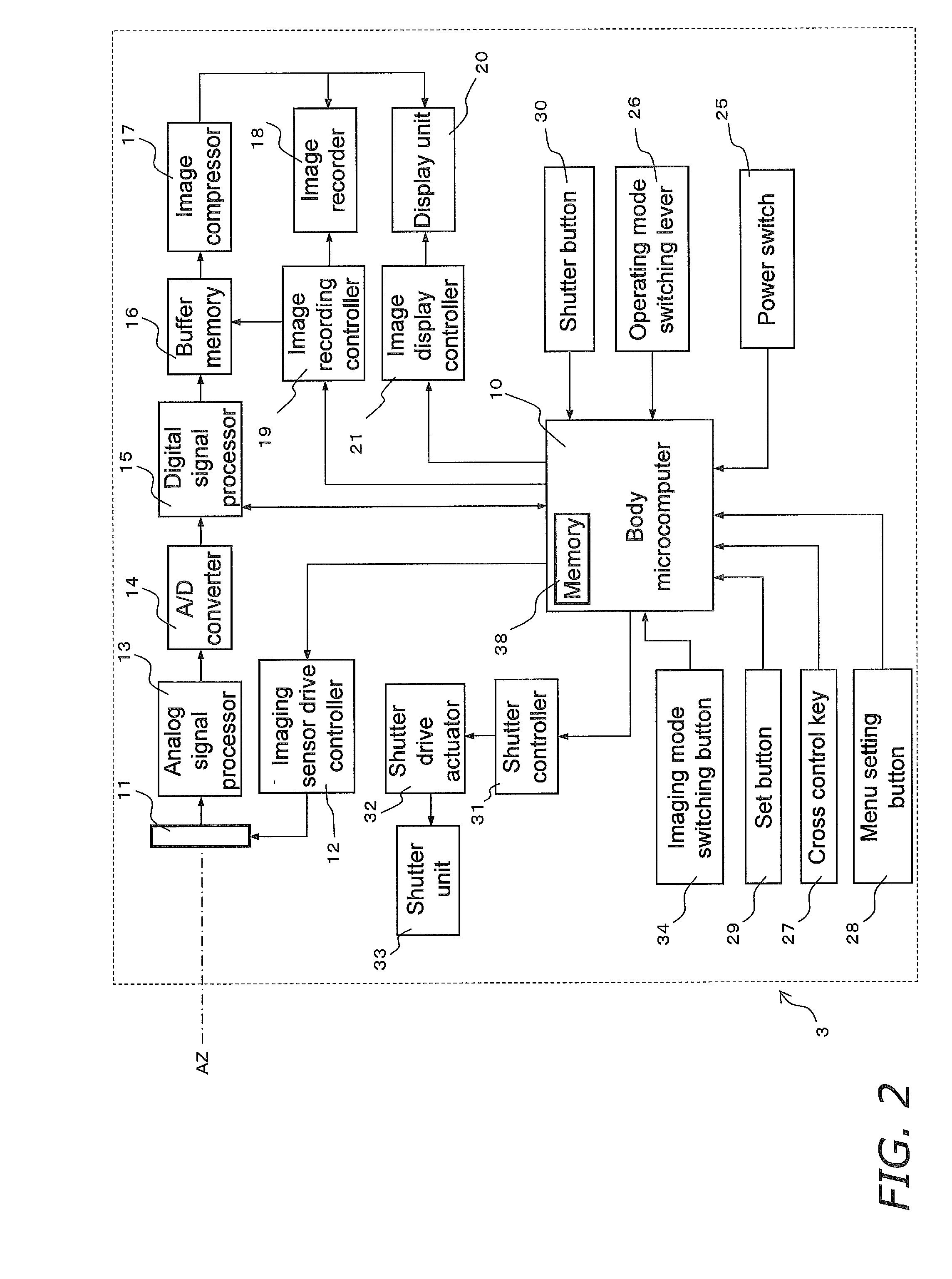
[0118]As shown in FIG. 1, a digital camera 1 (an example of an imaging device) is an interchangeable lens type of digital camera, and mainly has a camera body 3 having the primary function of the digital camera 1, and an interchangeable lens unit 2 (an example of a lens barrel) that is removably mounted to the camera body 3. The interchangeable lens unit 2 is mounted to a body mount 4 provided to the front face of the camera body 3, via a lens mount 71 provided to the rearmost part.

[0119]1.1: Interchangeable Lens Unit

[0120]As shown in FIG. 1, the interchangeable lens unit 2 has an optical system L, a zoom lens drive controller 97, a focus lens drive controller 41, an aperture drive controller 42, a lens microcomputer 40, a first rotation detector 65, and a second rotation detector 68.

[0121]The optical system L forms a subject image on an imaging sensor 11 of the camera body 3. The zoom lens drive controller 97 drives a first lens group L1 (d...

second embodiment

1: Object Distance Display

[0265]In the above embodiment, the zoom display bar 105 and the zoom display bar 125 express the focal length, but the same constitution is conceivable for the object distance of a subject that can be varied by the focus ring 67. A second embodiment will be described through reference to FIG. 18. FIG. 18 shows a focus display bar 205.

[0266]Components that have substantially the same function as in the constitution of the above embodiment will be numbered the same, and will not be described again in detail.

[0267]As shown in FIG. 18, the focus display bar 205 is disposed in the upper half of the display unit 20 area. More specifically, two lines that are perpendicular to each other and pass through the center C of the display unit 20 shall be termed a first line CL1 and a second line CL2. In the so-called landscape orientation, the first line CL1 is parallel to the horizontal direction, and the second line CL2 is parallel to the vertical direction. In the sta...

modification examples

3: Modification Examples

[0305]In the above embodiment, the focus display bar 205 was linear, but the focus display bar 205 may instead be arc-shaped.

[0306]For example, as shown in FIGS. 23 and 24, the object distance may be expressed using an arc-shaped focus display bar 225 (an example of a state indicator). This focus display bar 225 has a display meter 229 and a focus pointer 227. The display meter 229 has an arc-shaped meter box 229a whose center is the point ZC. The object distance is displayed around the meter box 229a. A display stripe 226 that is colored gray is formed by the meter box 229a and the focus pointer 227. The current object distance is expressed by the length of the display stripe 226.

[0307]The focus display bar 225 shown in FIG. 23 corresponds to the focus display bar 205 shown in FIGS. 18 and 19B. That is, the focus display bar 225 shown in FIG. 23 corresponds to a case in which the operation direction of the focus ring 67 in which the object distance increases...


PUM


Abstract

A camera body (3) includes a display unit (20) and a body microcomputer (10). The display unit (20) is able to display a zoom display bar (105) that expresses the focal length of the optical system (L). The body microcomputer (10) controls the display unit (20) so that the direction in which a zoom ring (64) moves when the user operates the zoom ring (64) substantially coincides with a change direction in which the zoom display bar (105) shown on the display unit (20) changes according to the operation of the zoom ring (64).

Description

TECHNICAL FIELD[0001]The present invention relates to an imaging device with which the state of the optical system can be varied.BACKGROUND ART[0002]Digital cameras with interchangeable lenses have surged in popularity in recent years. With these digital cameras, when the user looks at a subject through a viewfinder, the optical path is varied by a reflecting mirror. More specifically, light that has passed through the optical system (that is, the subject image) is reflected by a reflecting mirror disposed along the optical path. The reflected light goes through a pentaprism, etc., and is converted into an erected image, then guided to an optical viewfinder. This allows the user to see the subject image that has passed through the optical system by looking into the optical viewfinder. Therefore, the position at which the viewfinder optical path is formed is usually the home position of the reflecting mirror.[0003]On the other hand, when a lens is used for imaging, the reflecting mir...

Claims


Application Information

Patent Timeline
Patent Type & Authority Applications(United States)
IPC IPC(8): H04N5/222
CPCG02B7/021G02B7/023G03B17/14H04N5/23212H04N5/23293H04N5/23296H04N2101/00H04N5/23209H04N23/663H04N23/673H04N23/55H04N23/632H04N23/69
Inventor YUMIKI, NAOTO
Owner PANASONIC INTELLECTUAL PROPERTY MANAGEMENT CO LTD
Features
  • Generate Ideas
  • Intellectual Property
  • Life Sciences
  • Materials
  • Tech Scout
  • Unparalleled Data Quality
  • Higher Quality Content
  • 60% Fewer Hallucinations
Learn More