Ultra-low voltage boost circuit

Active Publication Date: 2010-08-19
NEMIR DAVID C
View PDF9 Cites 37 Cited by
  • Summary
  • Abstract
  • Description
  • Claims
  • Application Information

AI Technical Summary

Problems solved by technology

There are some devices that, due to size, weight or cost constraints, must operate off a single cell.
The disclosed embodiments draw power from the source only during alternating half cycles and have the further disadvantage of using a capacitor that is used as part of the self-start oscillator, thereby attenuating the voltage on a transistor gate, and preventing oscillation at very low voltages.

Method used


Image

  • Ultra-low voltage boost circuit
  • Ultra-low voltage boost circuit
  • Ultra-low voltage boost circuit

Examples


Embodiment Construction

[0103]In the following paragraphs, the present invention will be described in detail through examples and detailed drawings.

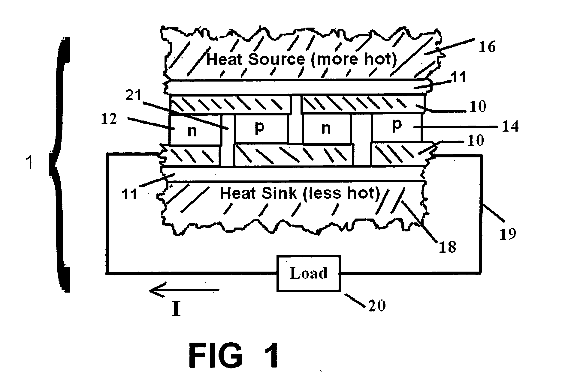
[0104]FIG. 1 depicts the side view of a thermoelectric generator. The generator is constructed by sandwiching specially chosen N and P type (equivalently n and p type) conductor or semiconductor material 12 and 14 between electrical conductors 10. Although these so-called thermoelements may be built using metals such as bismuth and antimony, higher efficiency thermoelectrics are built using heavily doped semiconductors. The electrical conductors 10 are chosen to be good conductors of both electricity and heat. When fabricated from a semiconductor material, the N type thermoelement 12 is formed by the introduction of a pentavalent chemical compound so that electrons are the majority electricity carrier. When fabricated from a semiconductor material, the P type thermoelement 14 is formed by the introduction of a trivalent chemical compound so that the majority el...


PUM


Abstract

A circuit for boosting the voltage from a very low level voltage source to a higher level voltage output utilizing self-oscillation.

Description

CROSS-REFERENCE TO RELATED APPLICATIONS[0001]This application is a continuation-in-part application of U.S. patent application Ser. No. 12 / 333,520 entitled “Surface Lighting Devices Having a Thermoelectric Power Source” which was filed on Dec. 12, 2008 and which claims the priority date of U.S. Provisional Patent Application Ser. No. 61 / 007,319 which was filed on Dec. 12, 2007. This application further claims the priority of U.S. Provisional Patent Application 61 / 214,778 filed Apr. 28, 2009, which is incorporated by reference as if written herein in its entirety.BACKGROUND OF THE INVENTION[0002]1. Field of the Invention[0003]This invention relates to an apparatus and method for boosting millivolt level voltages into higher voltages.[0004]2. Background of the Invention[0005]Voltage is a measurement of the electrical potential between two points.[0006]It is the driving force that causes electrical current to flow. Most battery powered electrical devices use one or more series connecte...

Claims


Application Information

Patent Timeline
Patent Type & Authority Applications(United States)
IPC IPC(8): H02M3/335
CPCH02M3/155H02M1/08
Inventor RUBIO, EDWARDHIRISH, STANLEY SIMONNEMIR, DAVID CHARLES
Owner NEMIR DAVID C
Why Eureka
Try Eureka