Communication terminal

a communication terminal and terminal technology, applied in the field of communication terminals, can solve the problems of waste of time resources and economic resources, and achieve the effect of alleviating the emotional burden of the user of the communication terminal and the user of the other terminal

Inactive Publication Date: 2010-08-19
SHARP KK
View PDF17 Cites 177 Cited by
  • Summary
  • Abstract
  • Description
  • Claims
  • Application Information

AI Technical Summary

Benefits of technology

[0041]As described above, according to the present invention, even when a call is once terminated, the communication terminal stores the identifier of the terminal of the other party of the call, and notifies the user of the state of the other party's terminal. Therefore, based on the notified state, it is possible for the user to constantly know when to resume the call to the other party's terminal. Thus, emotional burden both on the user of the communication terminal and the user of the other terminal can be alleviated.
[0042]Further, the communication terminal determines whether or not a prescribed time has passed from when the call with the other terminal once ends, and resumes the call with the other party in accordance with the result of determination. Therefore, if a call ends and the on-hold state begins, the user need not be kept for a long period in the emotionally unsettling state, in which he / she must keep in mind to refrain a call with a third party.
[0043]As a result, a communication terminal by which the party who put a call on hold and the party who is kept on hold are not kept in emotionally unsettling states, even if a call is put on-hold and the party who put the call on hold behaves thoughtlessly and leaves the call unattended, can be provided.

Problems solved by technology

Specifically, the general on-hold function involves two problems, that is, waste of time resource and waste of economical resource.

Method used


Image

  • Communication terminal
  • Communication terminal
  • Communication terminal

Examples


Embodiment Construction

[0055]In the following, embodiments of the present invention will be described in detail, with reference to the figures. In the description of embodiments below, the same components are denoted by the same reference characters. Their functions and names are also the same. Therefore, detailed description thereof will not be repeated.

[Network Environment]

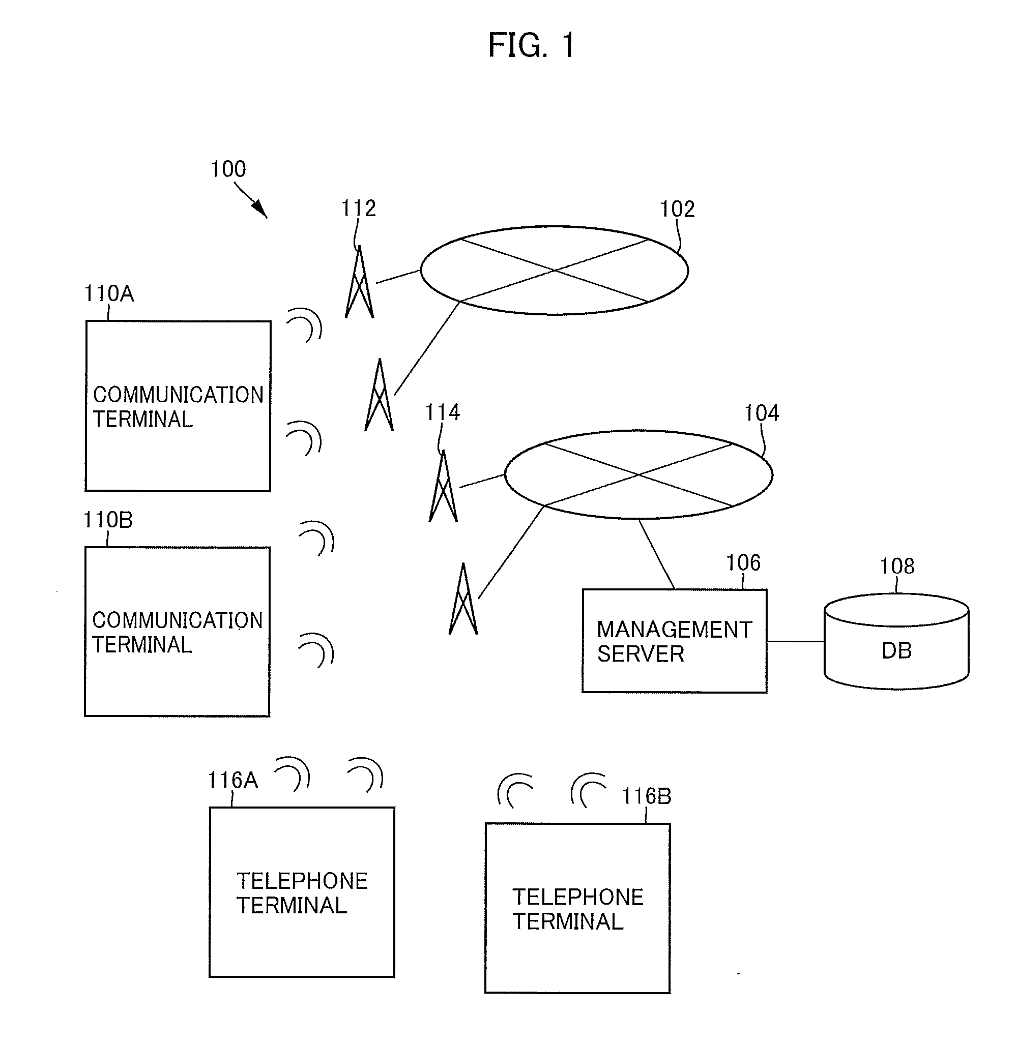
[0056]FIG. 1 schematically shows a configuration of a system 100 including a communication terminal in accordance with an embodiment of the present invention. Referring to FIG. 1, system 100 includes: a management server 106 connected to the Internet 104 and responsive to a request from an apparatus connected to the Internet 104, for controlling data transmission / reception between the apparatus and another apparatus connected to the Internet 104; and a DB 108 connected to management server 106 for storing various pieces of information of apparatuses connected to the Internet 104.

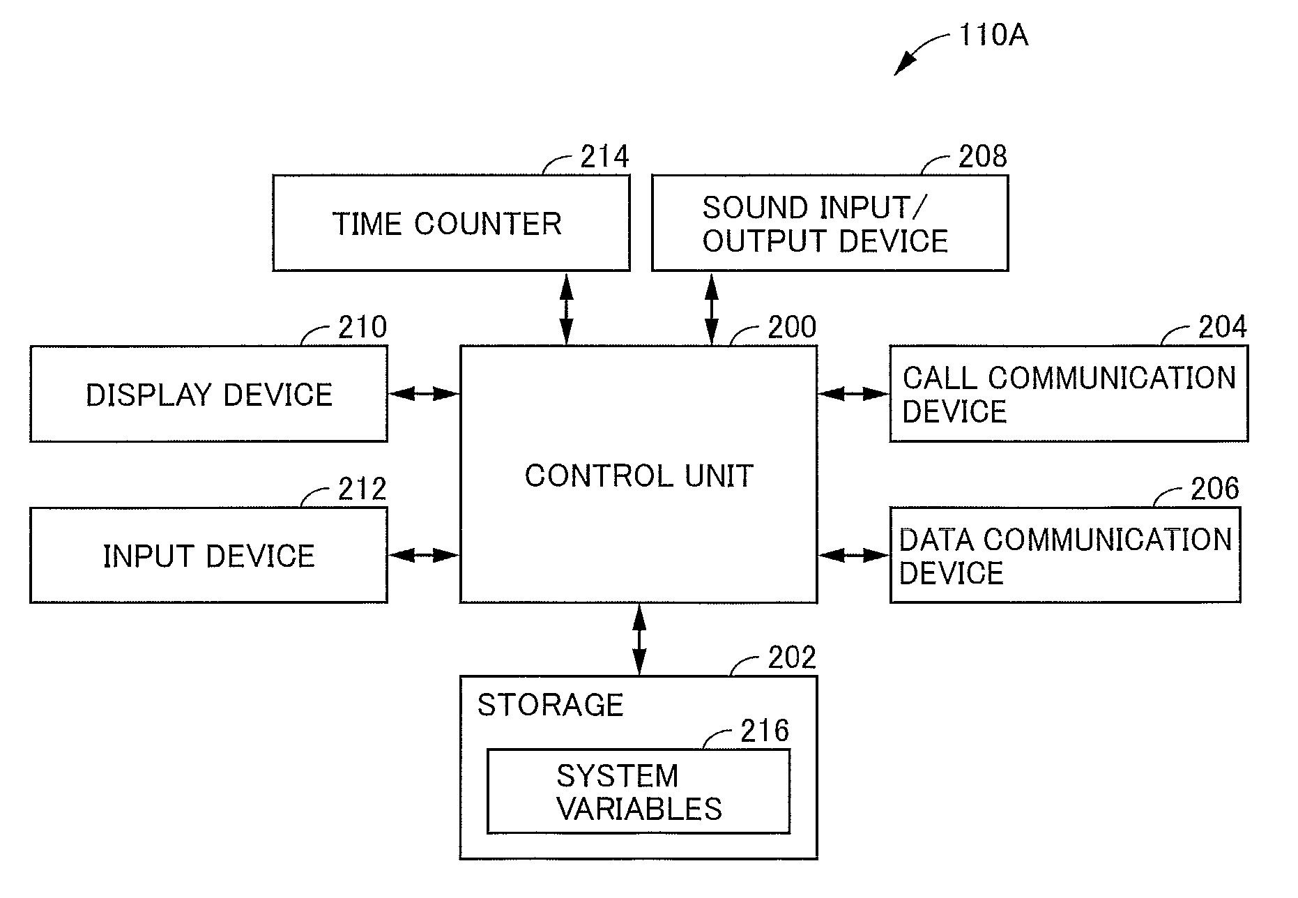
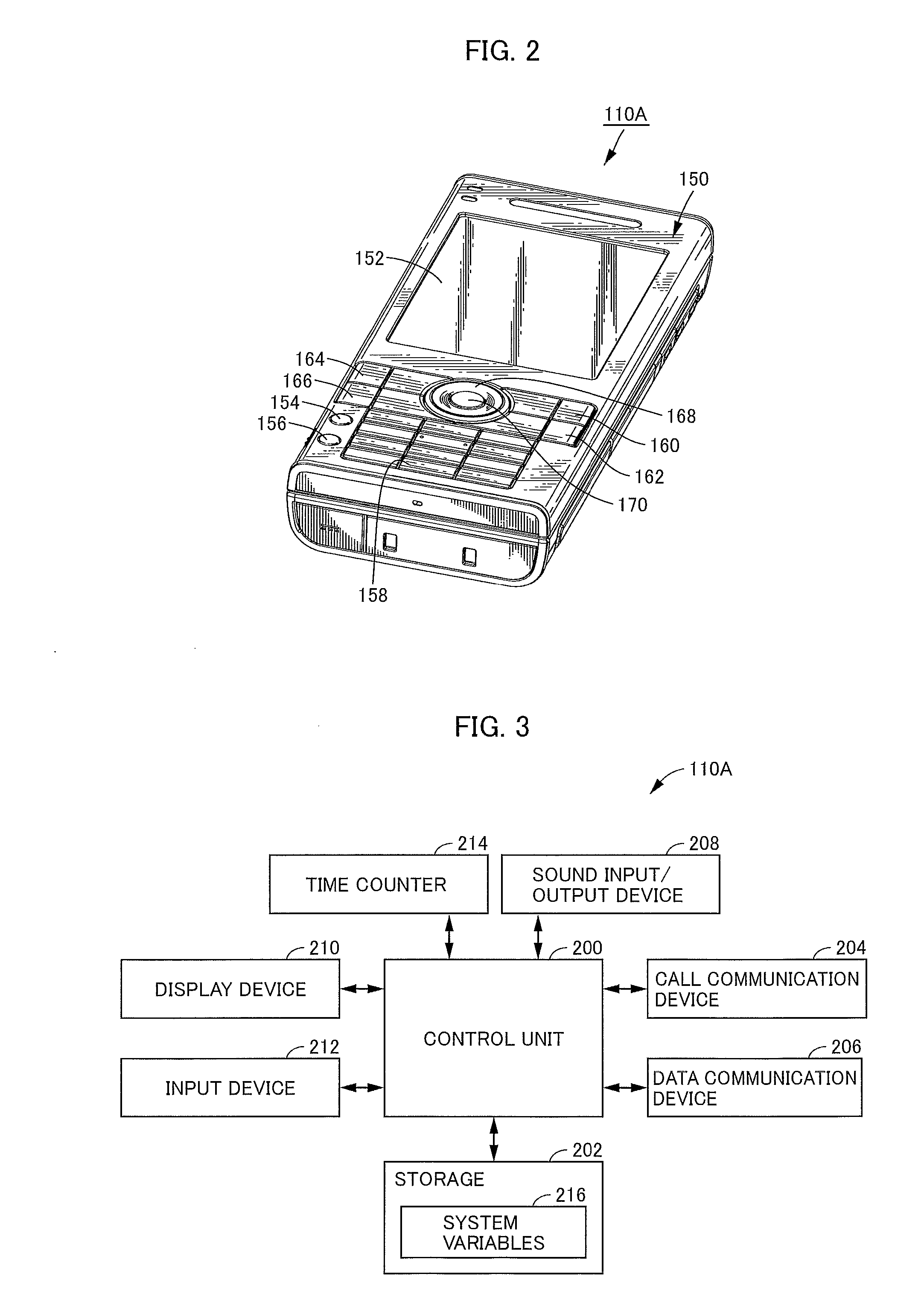
[0057]System 100 further includes communication terminal...


PUM


Abstract

A communication terminal 110A that can redial without imposing much emotional burden on the other party of the call even if the call is put on hold and the party who put the call on hold behaves thoughtlessly includes: a control unit 200 substantially implemented by a computer, for central control of communication terminal 110A, and a call communication device 204 for wireless voice communication with another terminal during a call with another terminal, a data communication device 206 for wireless data communication with another terminal and with management server 106, an input device 212 used by the user for operating communication terminal 110A, a time counter 214 for counting date and time, a display device 210, a sound input/output device 208, and a storage 202 for storing various pieces of information, all connected to the control unit 200.

Description

TECHNICAL FIELD[0001]The present invention relates to a communication terminal and, more specifically, to a communication terminal having a redialing function.BACKGROUND ART[0002]When a user consecutively makes telephone calls to the same party, in order to reduce burden on a user, the redialing function has been practically used.[0003]One of the redialing functions is to call a telephone number by allowing the user to designate a desired telephone number from call history. Specifically, a telephone number of a party who the user has called once is stored as call history, in the telephone. When the user makes a telephone call to the same party again, the user need not input the telephone number through ten keys, and the telephone makes a call to the telephone number among the call history, in response to a prescribed simple operation by the user such as pressing of a redial button.[0004]From the viewpoint that once a call ends, connection to a terminal that was once connected for a ...

Claims


Application Information

Patent Timeline
Patent Type & Authority Applications(United States)
IPC IPC(8): H04M3/42H04M1/724H04M1/72513H04M11/00
CPCH04M1/72513H04M1/82H04M1/72519H04M1/724
Inventor KAWAMURA, MISUZU
Owner SHARP KK
Why Eureka
Try Eureka