
Registration of 3D point cloud data to 2d electro-optical image data

a technology of electro-optical image data and point cloud data, applied in the field of image registration, can solve the problems of difficult and time-consuming image registration steps, lack of detailed visual information normally associated, and more complex cross-sensor registration problems

Inactive Publication Date: 2010-08-19
HARRIS CORP
View PDF74 Cites 79 Cited by
  • Summary
  • Abstract
  • Description
  • Claims
  • Application Information

AI Technical Summary

Benefits of technology

[0012]A transformation between the correspondence points is determined by minimizing the distance between the points using an error or cost function. This transformation is then applied to all data points in the 3D point cloud data. The result is that the 3D LIDAR point cloud data set is aligned with the two-dimensional EO image data set. This process can be applied in the other direction that is, a transformation can be found which aligns the EO to the 3D LIDAR.

Problems solved by technology

However, it often lacks much of the detailed visual information normally associated with image data acquired using conventional EO sensors.
However, combining the two different sets of imaging data necessarily requires an image registration step.
Still, this image registration step can be difficult and time consuming because it requires precise alignment of the EO and LIDAR image data acquired by different sensors at different data collection times and different relative sensor positions.
Moreover, the point cloud data is fundamentally different as compared to the EO image data, making for a more complex cross- sensor registration problem.
Second, using this 2D LIDAR intensity image along with the raw 3D point cloud data and the 2D EO image can be processing intensive and involve a substantial amount of computer memory.
Other 2D to 3D registration techniques are also limited in the sense that they are primarily useful only with urban scenes (and require shape information) or scenes involving medical imagery (and require markers on the 2D image).

Method used


Image

  • Registration of 3D point cloud data to 2d electro-optical image data
  • Registration of 3D point cloud data to 2d electro-optical image data
  • Registration of 3D point cloud data to 2d electro-optical image data

Examples


Embodiment Construction

[0024]The invention will now be described more fully hereinafter with reference to accompanying drawings, in which illustrative embodiments of the invention are shown. This invention, may however, be embodied in many different forms and should not be construed as limited to the embodiments set forth herein. For example, the present invention can be embodied as a method, a data processing system, or a computer program product. Accordingly, the present invention can take the form as an entirely hardware embodiment, an entirely software embodiment, or a hardware / software embodiment.

[0025]The present invention can be realized in one computer system. Alternatively, the present invention can be realized in several interconnected computer systems. Any kind of computer system or other apparatus adapted for carrying out the methods described herein is suited. A typical combination of hardware and software can be a general-purpose computer system. The general-purpose computer system can have ...


PUM


Abstract

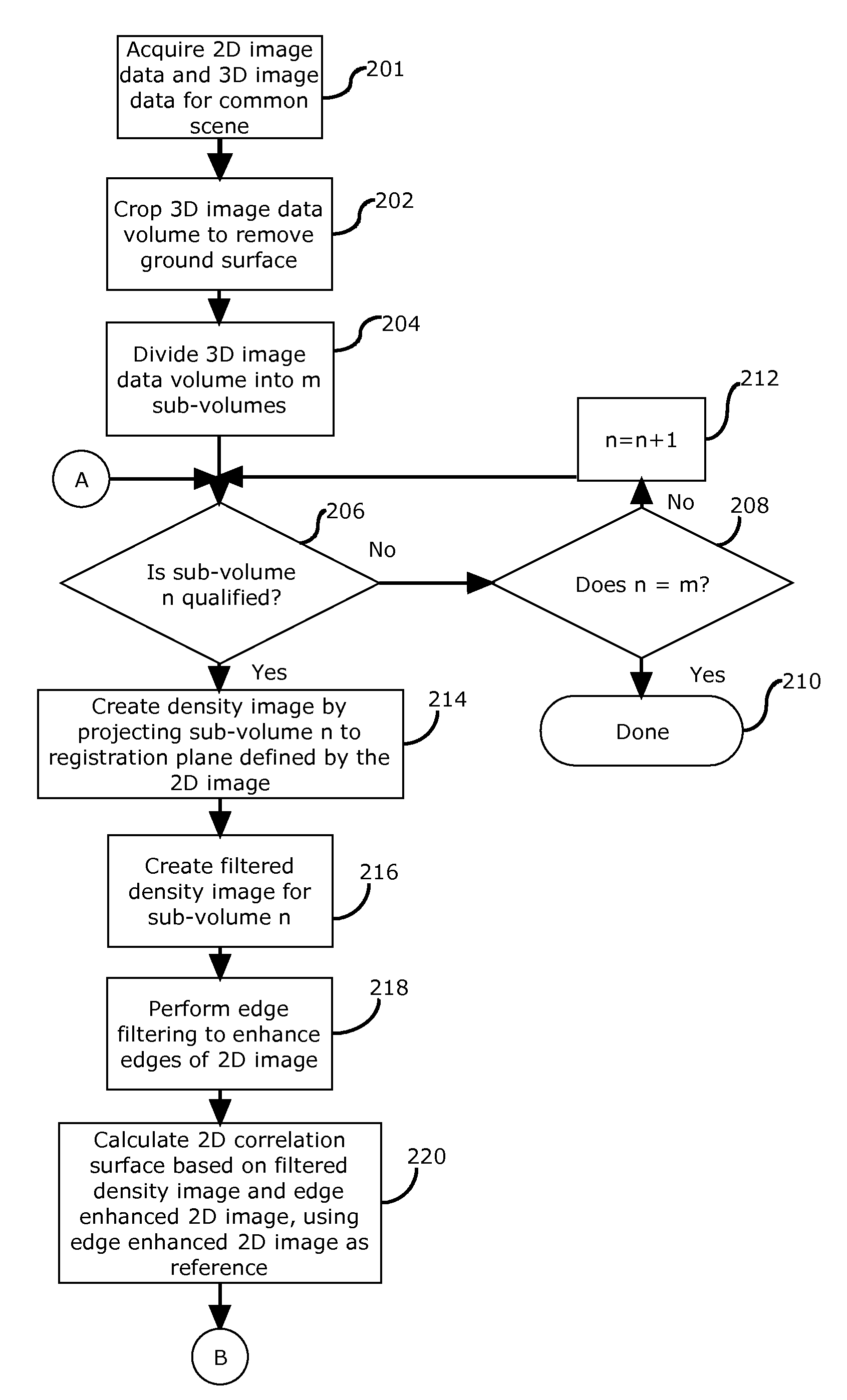
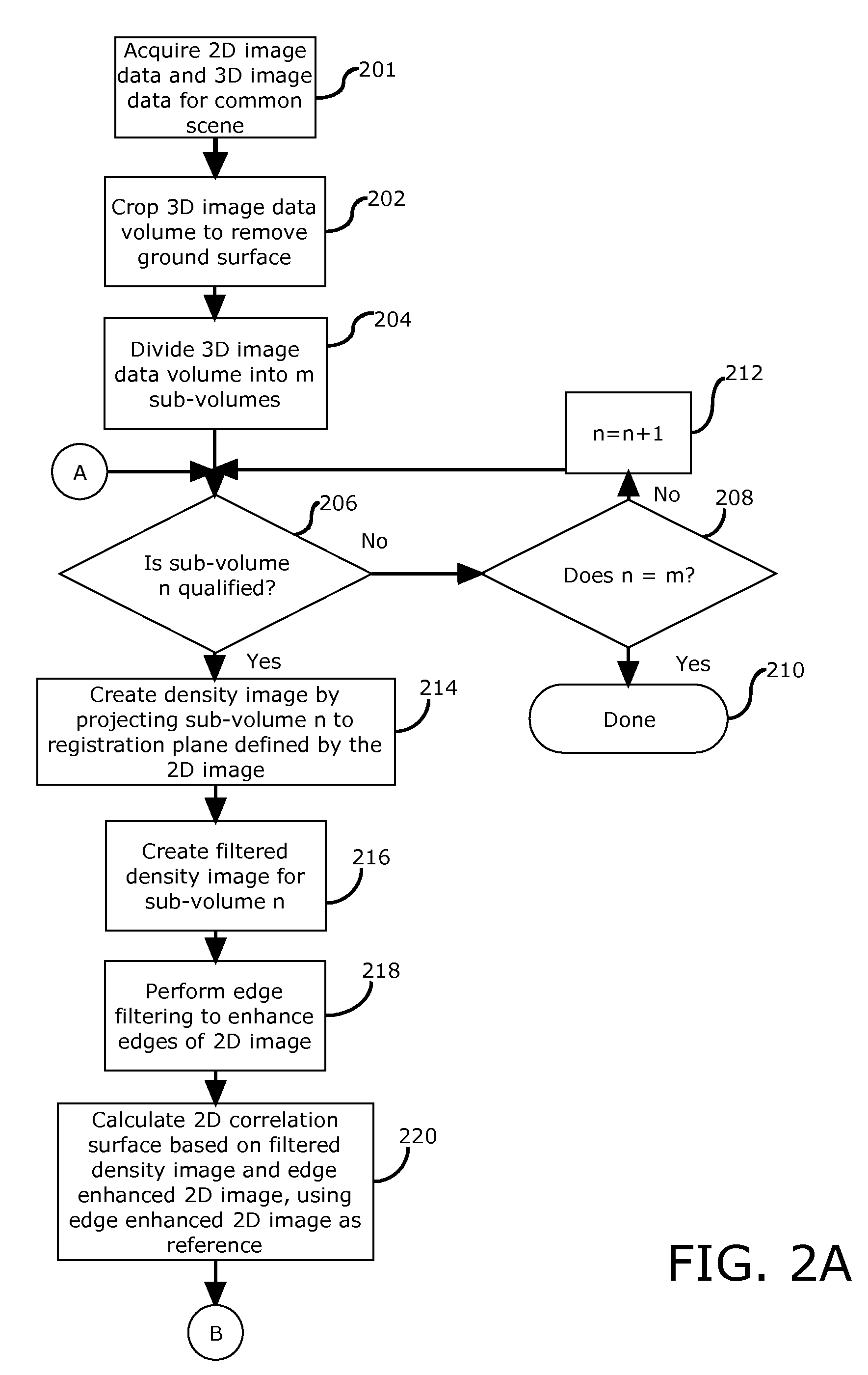
Method and system for registration of a two dimensional image data set and a three-dimensional image comprising point cloud data. The method begins by cropping a three-dimensional volume of point cloud data comprising a three-dimensional image data to remove a portion of the point cloud data comprising a ground surface within a scene, and dividing the three-dimensional volume into a plurality of m sub-volumes. Thereafter, the method continues by edge-enhancing a two-dimensional image data. Then, for each qualifying sub-volume, creating a filtered density image, calculating a two-dimensional correlation surface based on the filtered density image and the two-dimensional image data that has been edge enhanced, finding a peak of the two-dimensional correlation surface, determining a corresponding location of the peak within the two-dimensional image, defining a correspondence point set; and storing the correspondence point set in a point set list. Finally, a transformation is determined that minimizes the error between a plurality of the correspondence point sets contained in the point set list.

Description

BACKGROUND OF THE INVENTION[0001]1. Statement of the Technical Field[0002]The inventive arrangements concern image registration, and more particularly registration of two-dimensional image data acquired by electro-optical image sensors with three-dimensional point cloud image data acquired by LIDAR sensors.[0003]2. Description of the Related Art[0004]Imaging sensors are used in a wide variety of applications, including homeland security and military applications. For example, sensors of this type are commonly positioned on aircraft and earth-orbiting satellite platforms. Conventional electro-optical (EO) sensors have long been used for collection of such image data and generally produce two dimensional data. Such data generally corresponds to a projection of the image onto a planar field which can be entirely defined by an x and y coordinate axis.[0005]More recently, there has been a growing interest in three-dimensional imaging data Those skilled in the art will appreciate that the...

Claims


Application Information

Patent Timeline
IPC IPC(8): G06K9/40G06K9/32
CPCG06T7/0026G06T7/32G06T7/00
Inventor MINEAR, KATHLEENSMITH, ANTHONY O'NEIL
Owner HARRIS CORP
Learn More