Residential heat pump water heater

a technology of heat pump and water heater, which is applied in the direction of heat pump, heat pump, lighting and heating apparatus, etc., can solve the problems of undetectable hot water being drawn from the tank and the inability of the tank to be filled, and achieve the effect of facilitating the transfer of hea

Active Publication Date: 2010-08-19
HAIER US APPLIANCE SOLUTIONS INC
View PDF41 Cites 122 Cited by
  • Summary
  • Abstract
  • Description
  • Claims
  • Application Information

AI Technical Summary

Benefits of technology

[0004]Consistent with embodiments of the present invention, systems for controlling a heat pump water heater (HPWH) are disclosed. The systems are configured to heat water within a water storage tank of a heat pump water heater wherein a controller within the system is operatively connected to a heat pump and a pair of electric resistance heaters. The heat pump condenser is positioned proximate the water storage tank to facilitate the transfer heat from the condenser to the water in the water storage tank. A first electric resistance heater is positioned within the water storage tank in proximity to the bottom of the water storage tank. A second electric resistance heater is positioned within the water storage tank in proximity to the top of the water storage tank. The system further includes a temperature sensor positioned to determine the temperature of water within and in proximity to the top of the water storage tank. The controller includes a module configured to process data representative of temperature readings of water within the water storage tank. Upon processing temperature readings, the controller automatically selects and controls energizing of a heat pump condenser and the pair of electric heating elements. Data representative of the rate at which water flows into and from the water storage tank, the temperature of refrigerant, typically in a gas or vapor state entering a condenser and the temperature of refrigerant, typically at least partially in liquid state exiting the condenser is also processed by the controller. The controller automatically energizes one or more of the heat pump, the first electric resistance heater, and the second electric resistance heater in response to data processed.

Problems solved by technology

One of the problems with this configuration is that the sensor near the top of the tank can't detect that hot water is exiting and cold water is entering the tank near the bottom.
This causes the heated water to rise to the top creating a problem called stacking.
When this is occurring, the top part of the tank continues to get a little bit hotter each time which causes over heating of water in the top of the tank, which can potentially lead to undesirably hot water being drawn from the tank.

Method used


Image

  • Residential heat pump water heater
  • Residential heat pump water heater
  • Residential heat pump water heater

Examples


first embodiment

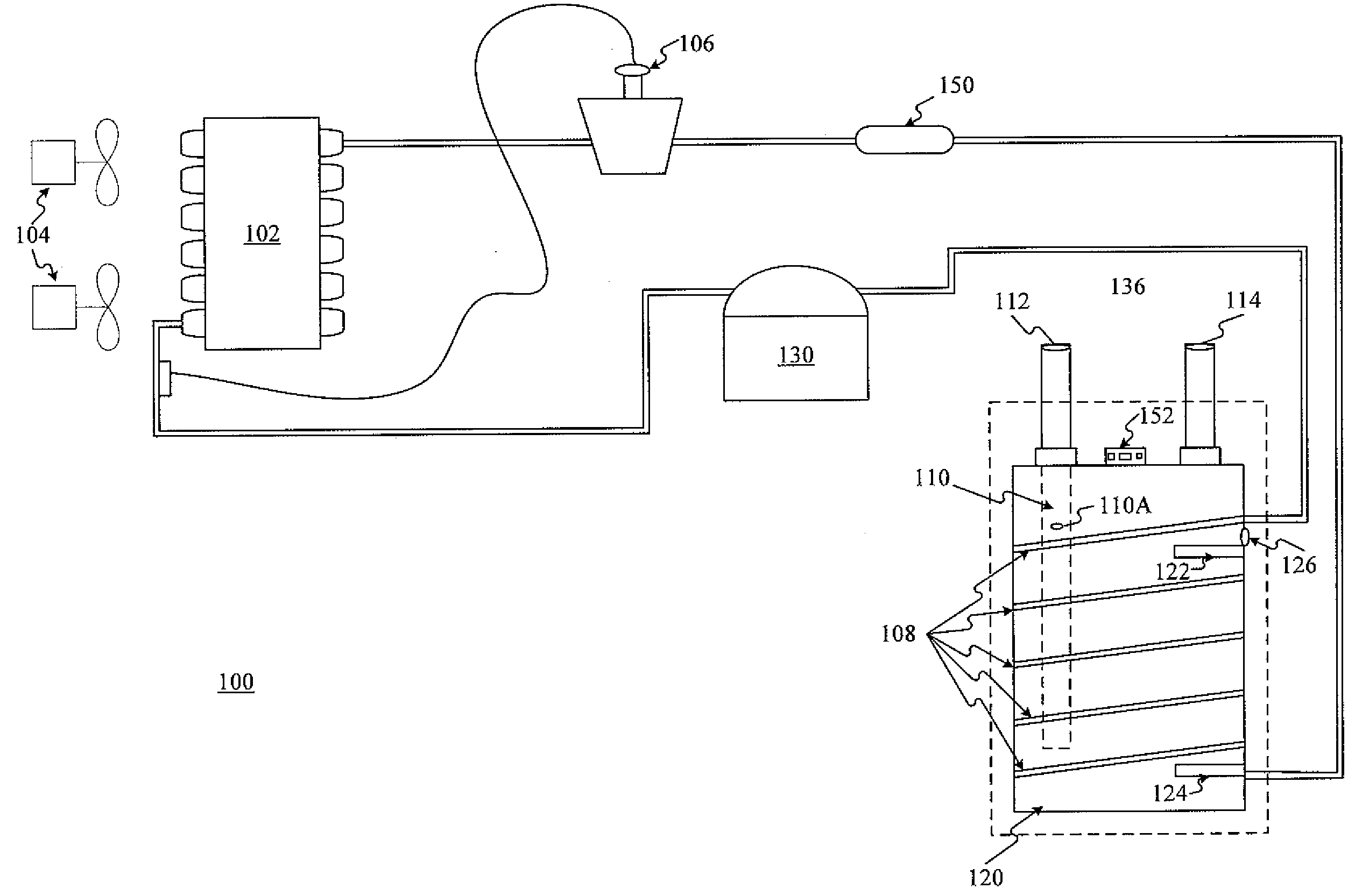
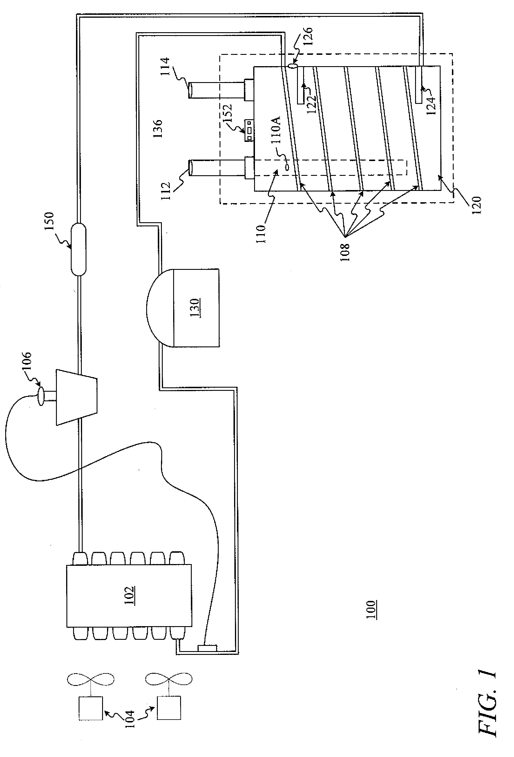
[0023]Referring now to the figures, FIG. 1 depicts a heat pump water heater 100 schematic consistent with the invention. The heat pump system comprises an evaporator 102, a compressor 130, a condenser 108, a throttling device 106, and at least one fan 104. Condenser 108 is assembled in a heat exchange relationship with the water in the water storage tank 120. During operation of the heat pump cycle a refrigerant exits the evaporator 102 as a fluid in the form of a superheated vapor and / or high quality vapor mixture. Upon exiting the evaporator 102 the refrigerant enters the compressor 130 where the pressure and temperature increase. The temperature and pressure are increased in the compressor 130 such that the refrigerant becomes a superheated vapor. The superheated vapor from the compressor 130 enters the condenser 108. While in the condenser 108, the superheated vapor transfers energy to the water within a storage tank 120. Upon transferring energy to the water within the storage ...

second embodiment

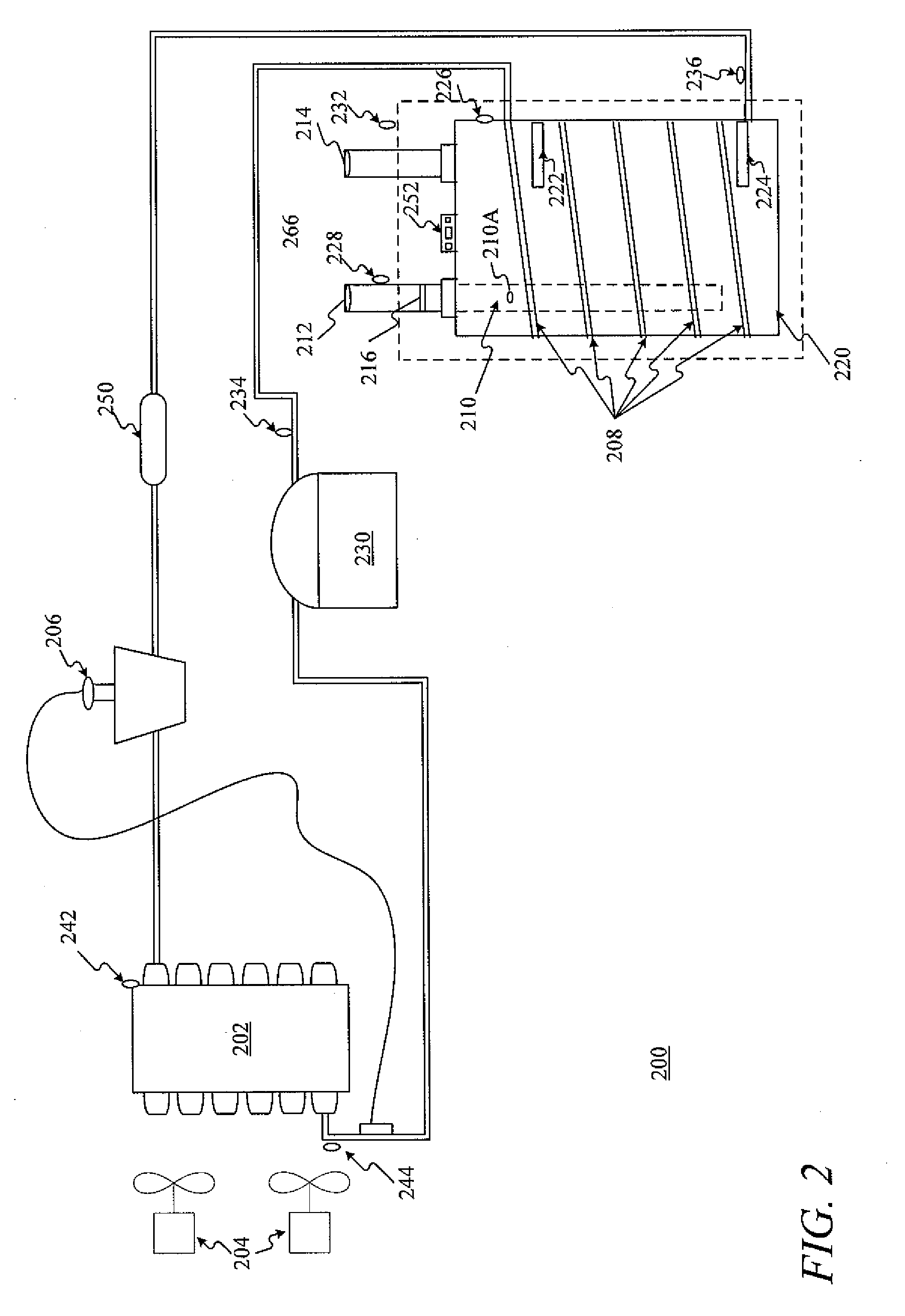
[0027]As illustrated in FIG. 2, the second embodiment includes a flow meter 216 positioned in the water inlet line 212. Flow meter 216 transmits data representative of the amount of water flowing into the water storage tank 220 to the water temperature and flow module within the controller 252. Under circumstances in which large amounts of water are removed from the water storage tank 220 in short periods of time, single sensor 226 may not read changes in water temperature at a speed that facilitates immediate recognition by the controller 252 that large amounts of water have been removed from the water storage tank 220. When large amounts of water are removed from water storage tank 220, the energizing of alternate and / or additional heating elements may be necessary in order to heat the water in the most efficient and timely manner. The controller 252 processes data representative of the rate of flow of water into the water storage tank 220 received from the flow meter 216 along wi...


PUM


Abstract

A heat pump water heater and systems and methods for its control are disclosed. The systems are configured to heat water within a water storage tank of a heat pump water heater wherein a controller within the system is operatively connected to a plurality of heat sources including at least one electric heating element and a heat pump and sensors in order to selectively energize one of the plurality of heat sources. The controller is configure to process data representative of the temperature of water within the tank near the top of the water storage tank, and rate of water flowing out of the water storage tank, in order to automatically selectively energize the heat sources. The selection of heat sources by the controller is determined by a mode of operation selected by the user and the data processed by the controller in view of the selected mode of operation.

Description

FIELD OF INVENTION[0001]Embodiments of the present invention relate to water heaters. More specifically, embodiments of the present invention relate to heat pump water heaters.BACKGROUND OF THE INVENTION[0002]A widely accepted and used water heater for residential hot water production and storage is the electric resistance water heater and storage tank. Water heaters typically include a tank defining a chamber for retention of water. A water inlet pipe that is provided with a first connection for interconnection with a cold water supply line that conveys fresh relatively cold water into the chamber. Within the tank there are electric resistance elements that heat the water in the tank. In current embodiments, there are at least two electric resistance elements. A first electric resistance element positioned near the bottom of the tank and a second electric resistance element positioned near the top of the tank. There are also two sensors positioned on the exterior of the tank that m...

Claims


Application Information

Patent Timeline
Patent Type & Authority Applications(United States)
IPC IPC(8): F24H1/10F25B27/00F24H4/00
CPCF24D2200/08F24D2200/12F24H4/04F24H9/2007F25B30/02F24D19/1054F25B2400/01F25B2700/21161F24D17/0031F24D17/02F25B2339/047Y02B30/12F24H15/429F24H15/38F24H15/223F24H15/35F24H15/238F24H15/37F24H15/231F24H15/12F24H15/132F24H15/215
Inventor NELSON, JONATHAN D.TSAI, CRAIG LUNG-PEIKERN, JEFFREY ALANRODRIGUEZ, ELIEL FRESCOBEYERLE, MICHEAL T.WATKINS, DEREK LEEHAMEL, TIMOTHY ALLENZENTNER, MARTIN
Owner HAIER US APPLIANCE SOLUTIONS INC
Why Eureka
Try Eureka