
Methods for heating with lamps

Active Publication Date: 2010-08-19
ALTA DEVICES INC
View PDF20 Cites 24 Cited by
  • Summary
  • Abstract
  • Description
  • Claims
  • Application Information

AI Technical Summary

Benefits of technology

[0011]Embodiments of the method further provide that the heating lamp assembly contains lamps which have a split filament lamp, a non-split filament, or a mixture of lamps which contain either split or non-split filaments. In one embodiment, each of the lamps has a split filament lamp. The split filament lamp may have a center between a first end and a second end. The first and second ends of the split filament lamps may be maintained warmer than the centers of the split filament lamps. Therefore, outer edges of the substrate susceptor may be maintained warmer than a center point of the substrate susceptor.
[0012]In another embodiment, each of the lamps has a non-split filament lamp. The non-split filament lamp may have a center between a first end and a second end. The centers of the non-split filament lamps may be maintained warmer than the first and second ends of the non-split filament lamps. Therefore, a center point of the substrate susceptor may be maintained warmer than the outer edges of the substrate susceptor.
[0014]In various embodiments, the method provides that the substrate susceptor may be a substrate carrier or a wafer carrier. The lamp housing may have a first lamp holder and a second lamp holder. The first lamp holder and the second lamp holder may be parallel or substantially parallel to each other. In one example, the reflector may be disposed between the first lamp holder and the second lamp holder. The first lamp holder and the second lamp holder each have a thickness within a range from about 0.001 inches to about 0.1 inches. The predetermined thickness of the lamp holders helps maintain a constant temperature of the lamp holders. Therefore, the first lamp holder and the second lamp holder may each independently be maintained at a temperature within a range from about 250° C. to about 400° C., preferably, from about 275° C. to about 375° C., preferably, from about 300° C. to about 350° C.

Problems solved by technology

These distinct designs address a variety of challenges that are encountered during a CVD process, such as depletion effects, contamination issues, reactor maintenance, throughput, and production costs.

Method used


Image

  • Methods for heating with lamps
  • Methods for heating with lamps
  • Methods for heating with lamps

Examples


Embodiment Construction

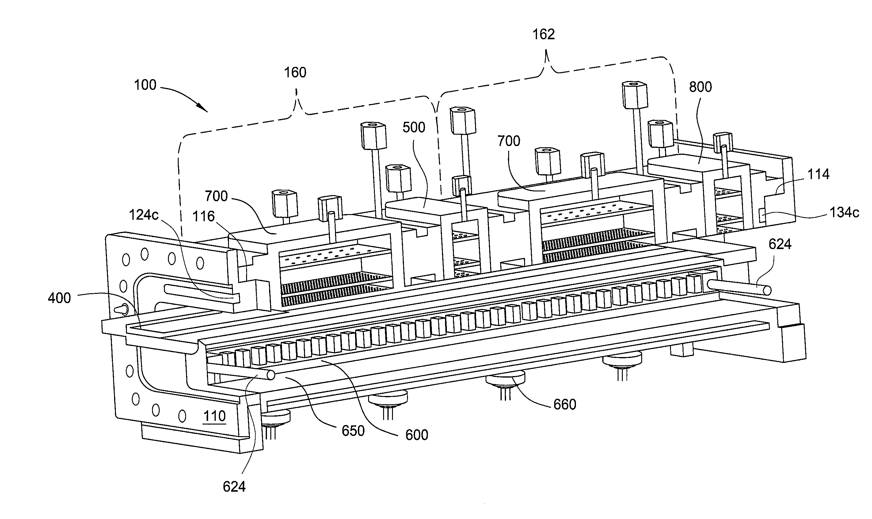
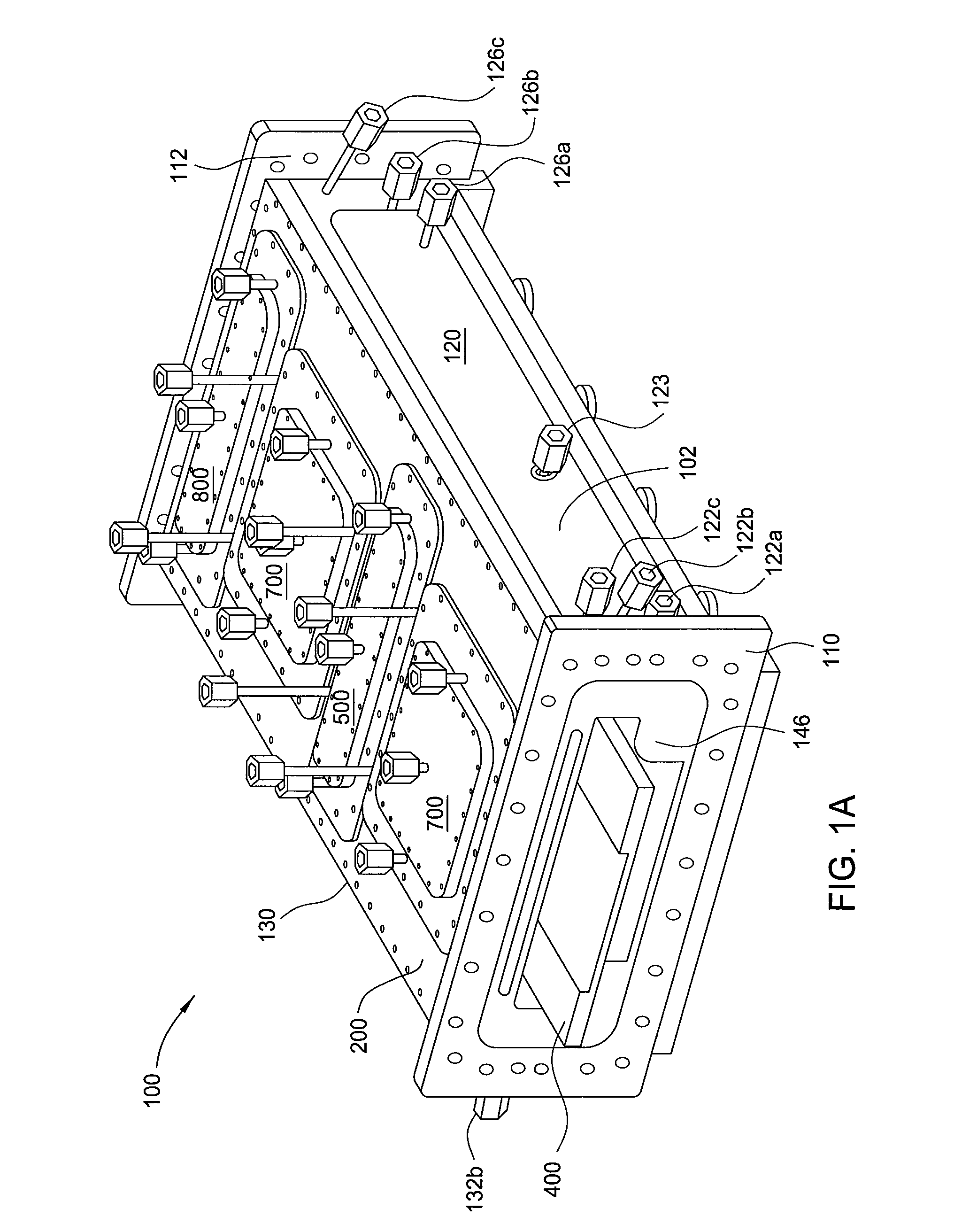
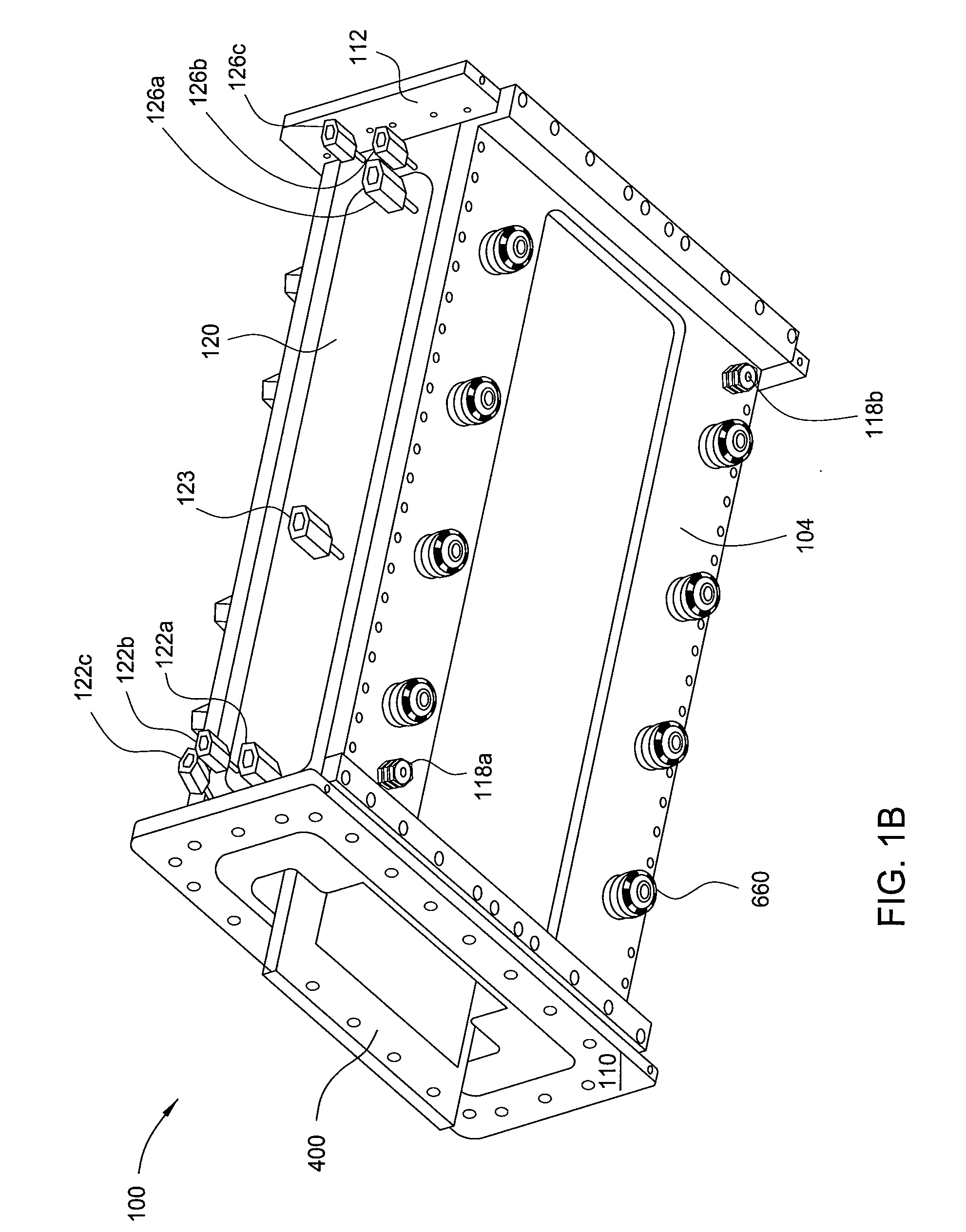
[0033]Embodiments of the invention generally relate to an apparatus and methods of chemical vapor deposition (CVD), such as metallic-organic CVD (MOCVD) processes. As set forth herein, embodiments of the invention are described as they relate to an atmospheric pressure CVD reactor and metal-organic precursor gases. It is to be noted, however, that aspects of the invention are not limited to use with an atmospheric pressure CVD reactor or metal-organic precursor gases, but are applicable to other types of reactor systems and precursor gases. To better understand the novelty of the apparatuses of the invention and the methods of use thereof, reference is hereafter made to the accompanying drawings.

[0034]According to one embodiment of the invention, an atmospheric pressure CVD reactor is provided. The CVD reactor may be used to provide multiple epitaxial layers on a substrate, such as a gallium arsenide substrate. These epitaxial layers may include aluminum gallium arsenide, gallium ar...


PUM

PropertyMeasurementUnit
thicknessaaaaaaaaaa
temperatureaaaaaaaaaa

Abstract

Embodiments of the invention generally relate to methods for chemical vapor deposition (CVD) processes. In one embodiment, a method for heating a substrate or a substrate susceptor within a vapor deposition reactor system includes exposing a lower surface of a substrate susceptor, such as a wafer carrier, to energy emitted from a heating lamp assembly, and heating the substrate susceptor to a predetermined temperature. The heating lamp assembly generally contains a lamp housing disposed on an upper surface of a support base and contains at least one lamp holder, a plurality of lamps extending from the lamp holder, and a reflector disposed on the upper surface of the support base, next to the lamp holder, and below the lamps. The plurality of lamps may have split filament lamps and / or non-split filament lamps for heating inner and outer portions of the substrate susceptor.

Description

CROSS-REFERENCE TO RELATED APPLICATIONS[0001]This application claims benefit of U.S. Provisional Application Nos. 61 / 160,690, 61 / 160,694, 61 / 160,696, 61 / 160,699, 61 / 160,700, 61 / 160,701, and 61 / 160,703, all of which were filed Mar. 16, 2009, and all of which are hereby incorporated by reference in their entirety.[0002]This application is also a continuation-in-part of U.S. application Ser. Nos. 12 / 475,131, and 12 / 475,169, both filed May 29, 2009, and both claim benefit of U.S. Provisional Application No. 61 / 057,788, filed May 30, 2008, U.S. Provisional Application No. 61 / 104,284, filed Oct. 10, 2008, and U.S. Provisional Application No. 61 / 122,591, filed Dec. 15, 2008, and all of which are hereby incorporated by reference in their entirety.BACKGROUND OF THE INVENTION[0003]1. Field of the Invention[0004]Embodiments of the invention generally relate to apparatuses and methods for vapor deposition, and more particularly, to chemical vapor deposition systems, reactors, and processes ther...

Claims


Application Information

Patent Timeline
Patent Type & Authority Applications(United States)
IPC IPC(8): C23C16/46
CPCC23C16/4412C23C16/45519C23C16/45565C23C16/4583C23C16/481H01L21/67784C30B25/025C30B25/10C30B29/40C30B29/42H01L21/67115C23C16/54
Inventor HE, GANGHIGASHI, GREGGSORABJI, KHURSHEDHAMAMJY, ROGERHEGEDUS, ANDREAS
Owner ALTA DEVICES INC
Features
  • Generate Ideas
  • Intellectual Property
  • Life Sciences
  • Materials
  • Tech Scout
  • Unparalleled Data Quality
  • Higher Quality Content
  • 60% Fewer Hallucinations
Learn More