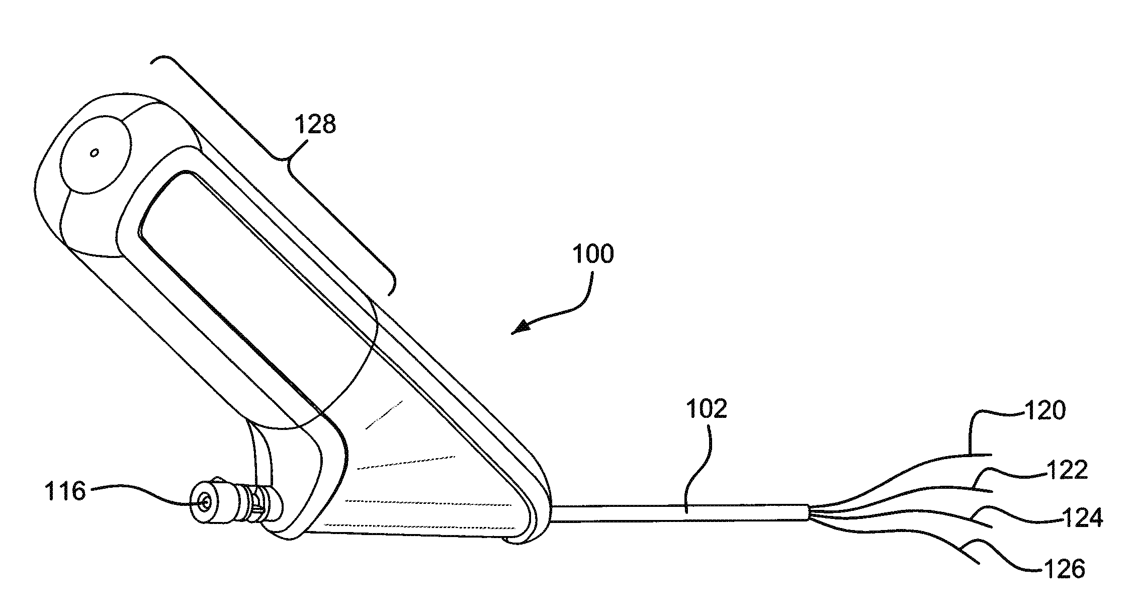
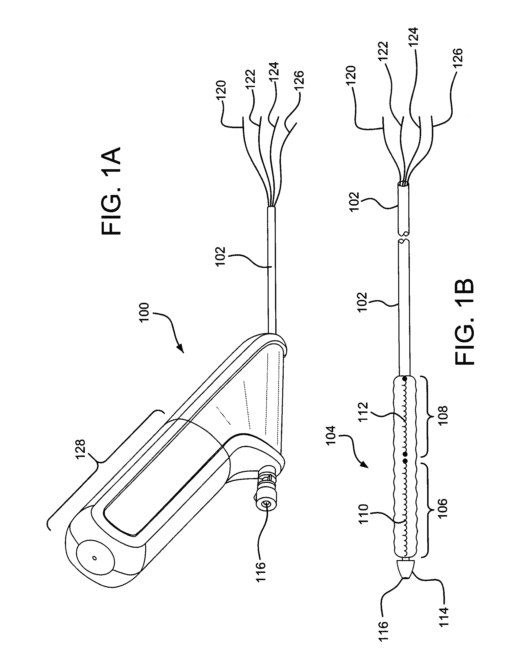
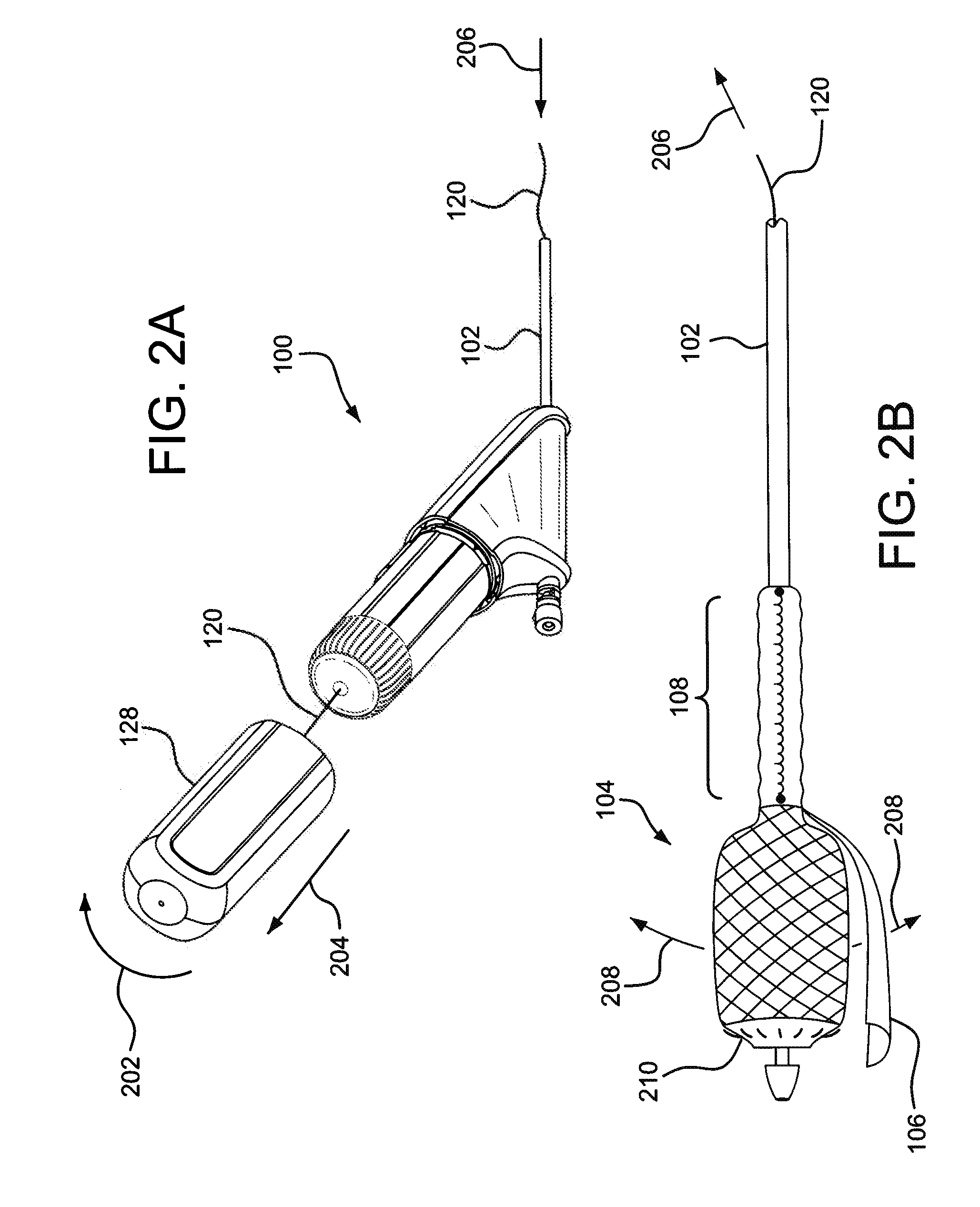
Forced deployment sequence

a deployment sequence and force technology, applied in the field of tools, can solve the problems of inadvertent user errors, and the inability to disclose a tool or an operational handle that fails to protect,

Active Publication Date: 2010-08-19
WL GORE & ASSOC INC
View PDF38 Cites 91 Cited by
  • Summary
  • Abstract
  • Description
  • Claims
  • Application Information

AI Technical Summary

Benefits of technology

[0007]The invention provides an interlocked control handle that forces a predetermined activation sequence.

Problems solved by technology

Nazari does not disclose a tool or operational handle that fail-safes the deployment sequence.
Despite

Method used


Image

  • Forced deployment sequence
  • Forced deployment sequence
  • Forced deployment sequence

Examples


example 1

[0052]A fixture, according to one embodiment of the present invention, was fabricated to test cable retention forces. As shown in top view FIG. 10A and perspective view 10B, an attachment feature 1000 was assembled having a substrate 1002. The substrate 1002 had a cavity 1006, sized to accept a cable 1008 and a retention sphere 1004. FIGS. 10C and 10D are sectional views taken along the centerline of cavity 1006. As shown, a cable 1008 was placed into the cavity 1006. A ball bearing 1004 was then pressed into the cavity 1006, deforming the cable as shown in FIG. 10D. A medical grade UV curable adhesive was then dispensed into the cavity, partially enmembersulating the cavity, ball bearing and the deformed cable.

example 2

[0053]The fixture from Example 1 was fitted with cable sections, ball bearings were pressed into the cavities and an adhesive was applied as an overcoat. The compressive loads required to press and seat the ball bearings were recorded using an Ametek® (Paoli, Pa.) Chatillion® DFX-050 compression gage. After curing the adhesive, the cables were tensioned to determine the retention load. The cables were tensioned using an Instron® (Norwood, Mass.) tensile tester and load cell. Twenty assemblies were evaluated.


PUM


Abstract

A fixed sequence activation handle is described that forces a predetermined activation sequence. Such handles are suitable for use in the delivery of medical devices or for other application that require a fixed sequence of activations.

Description

CROSS-REFERENCE TO RELATED APPLICATIONS[0001]This application claims benefit to U.S. Provisional Patent Application Ser. No. 61 / 145,693 filed Jan. 19, 2009, which is incorporated by reference herein for all purposes.BACKGROUND OF THE INVENTION[0002]1. Field of the Invention[0003]The invention relates to a tool having a fixed sequence of activation steps. In particular the invention relates to medical device deployment handles that intend to eliminate practitioner errors of delivery sequence in deployment of a medical device.[0004]2. Discussion of the Related Art[0005]Endovascular medical devices that require a specific series of steps to complete the delivery are known in the art. For example the vascular prosthesis disclosed in U.S. Pat. No. 5,554,184 to Nazari has several control lines that are required to be activated in a particular sequence to affect proper deployment of the device. Nazari does not disclose a tool or operational handle that fail-safes the deployment sequence. S...

Claims


Application Information

Patent Timeline
IPC IPC(8): A61B17/00
CPCA61F2/95A61F2002/9505A61F2002/9511F16C1/102F16G11/048A61F2/958A61F2002/9517Y10T74/20462A61F2/9517
Inventor BROWN, HAROLD A.DAVIS, ERIC J.GENDRON, MICHELLE L.LOEWEN, JOHN L.LONG, CLARE R.SOKEL, JUSTIN W.SULLIVAN, JOSEPH P.WIERZOCH, MARKUS
Owner WL GORE & ASSOC INC
Why Eureka
Try Eureka