Storage system, volume management method, and management computer

a storage system and volume management technology, applied in the field of storage systems and volume management methods, can solve the problems of liable problems and the inability to reduce the file system, and achieve the effects of optimizing the capacity of the file system, and efficiently utilizing the properties of the volumes/file systems

Active Publication Date: 2010-08-19
HITACHI LTD
View PDF4 Cites 14 Cited by
  • Summary
  • Abstract
  • Description
  • Claims
  • Application Information

AI Technical Summary

Benefits of technology

[0017]In order to solve the above mentioned problems, a management computer (i.e., capacity management computer 120) of the storage system collects information of a file system on performance, function and previous capacity changing history, for a file system group sharing a storage apparatus. The management computer estimates a time until available capacity of the respective file systems comes to be insufficient, and calculates capacity of the file system, which mostly elongates the time to cause a shortage of the available capacity. Then, the management computer executes reducing and expanding processes of the respective file systems.
[0018]Further, the management computer calculates capacity of the file system in the respective properties by using the information collected as mentioned above, in a configuration where there are a plurality of volumes / file systems in different properties. Then, the management computer calculates the optimized capacity of the file system so as to efficiently utilize the properties of the volumes / file systems for the whole system.
[0019]If a file system needs only a smaller capacity than the current capacity, the management computer makes a file in the file system migrate to a file system having a different property to increase the available capacity in the file system. Further, the management computer reduces the file system whose available capacity is made increased, and optimizes the capacity of the whole system by allocating the volume capacity coming to be unused, to another file system.
[0020]According to the present invention, in a file system group of sharing a storage apparatus, it is possible to optimize capacity configuration of the file systems in the whole system, reducing a load accompanied by a capacity change of the file system.
[0021]Further, if the storage apparatus has volumes / file systems with different properties as mentioned above, it is possible to distribute the capacity among the volumes / file systems so as to optimize effects of good properties in the whole system.

Problems solved by technology

Herein, the overhead represents a process needed indirectly and additionally when the process is carried out, and a size of the load caused by the process.
If a computer A needs more capacity of the high speed volume due to a performance issue, the computer A needs available capacity to be distributed from the high speed volume used by the other computer B. Herein, even if there is no available capacity in the file system, reduction of the file system can not be conducted.
This kind of problem is liable to happen, when a capacity arrangement is performed among volumes / file systems whose reliability and function in addition to performance are different.

Method used


Image

  • Storage system, volume management method, and management computer
  • Storage system, volume management method, and management computer
  • Storage system, volume management method, and management computer

Examples


first embodiment

[0039]Hereinafter, a first embodiment of the present invention will be explained.

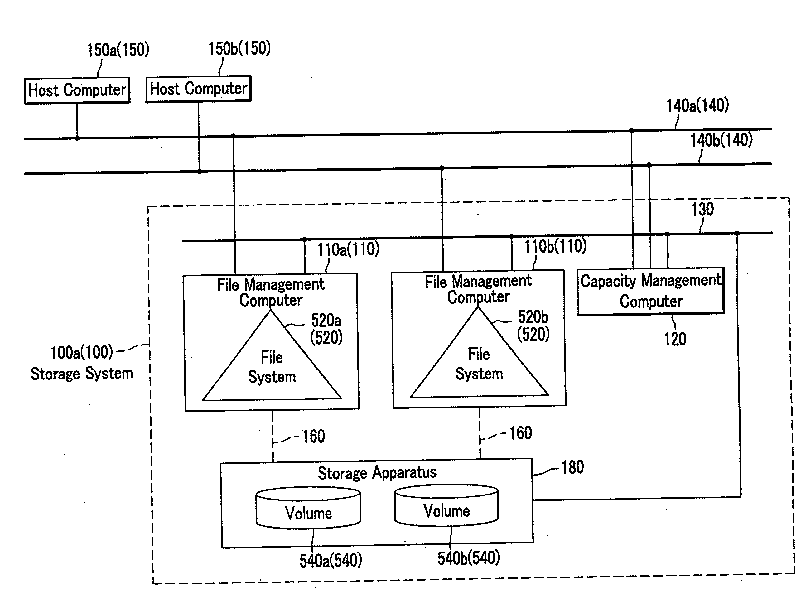
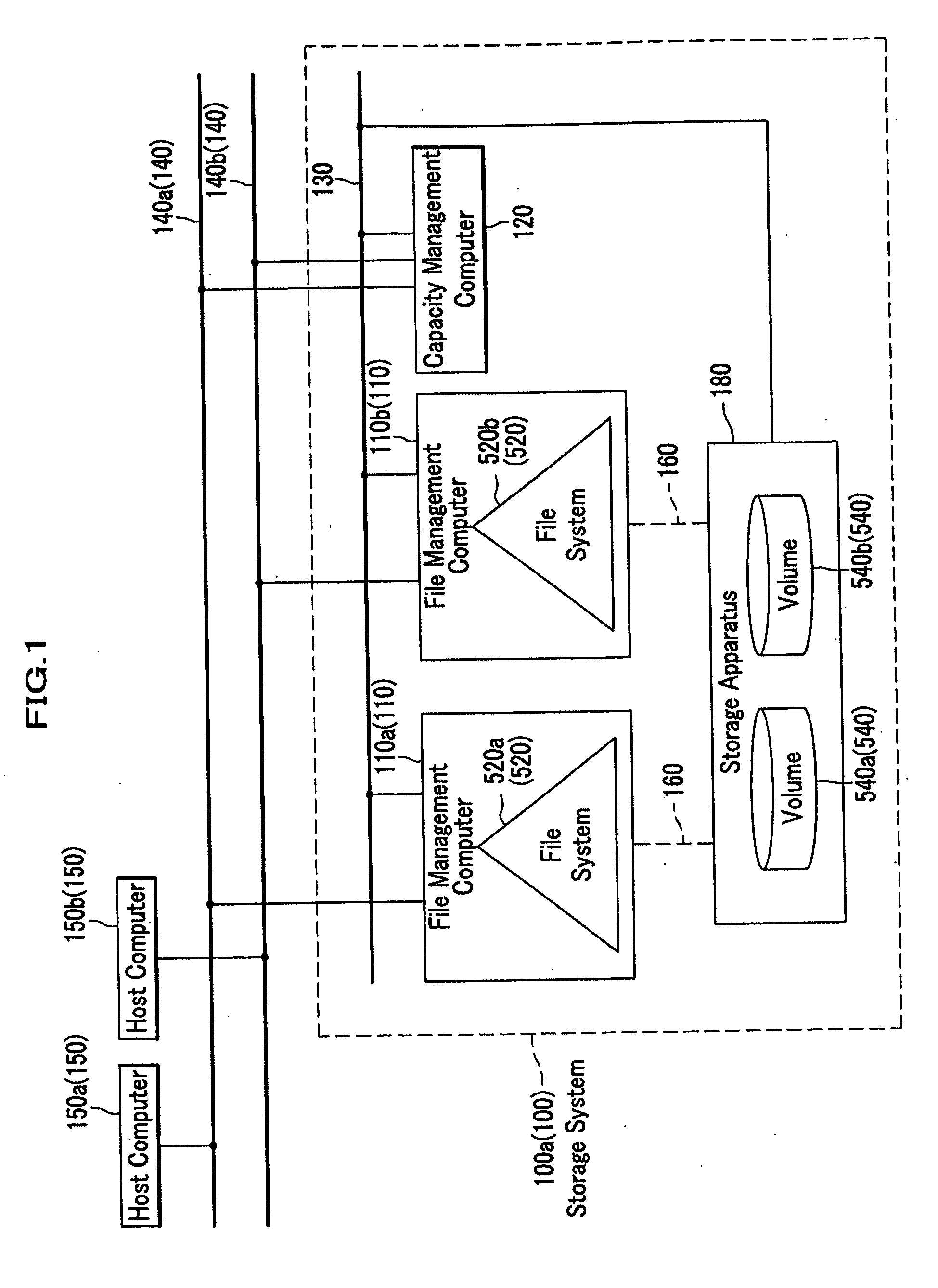
[0040]FIG. 1 is a block diagram showing a configuration example of a computer system including a storage system in the first embodiment. As shown in FIG. 1, the storage system 100a (100) comprises file management computers 110a (110) and 110b (110), a storage apparatus 180, a capacity management computer 120, wires 160, and a management network 130 for management. The storage system 100a (100) provides a file storage function to host computers 150a (150) and 150b (150) which are coupled to data networks 140a (140) and 140b (140). The file management computers 110a and 110b, which are applicable subject matters of the present invention, are computers provided with file systems 520a (520) and 520b (520) respectively. The storage apparatus 180 has a storage medium and provides a storage area with the file management computers 110a and 110b. Here, the file systems 520 will be explained later referring to FI...

second embodiment

[0104]Hereinafter, a second embodiment of the present invention will be explained.

[0105]According to the second embodiment, when files are transferred among the file systems, the storage system can use a mechanism that a change in a file name is concealed from outside computers, and an input / output operation to the file is possible by using the same file name before / after the files are transferred. Regarding methods for concealing the name change, Japanese Laid-Open Patent Application No. 2006-216070, and Japanese Laid-Open Patent Application No. 2006-164211 disclose the methods. In the second embodiment, the respective methods will be explained by presenting a first example of the concealing mechanism of the name change (see FIGS. 14 and 15), and a second example of the concealing mechanism of the name change (see FIG. 16).

[0106](Example of First Concealing Mechanism of Name Change)

[0107]FIG. 14 is a block diagram showing a configuration example of a computer system including the s...


PUM


Abstract

A storage system for optimizing volume capacity among file management computers of sharing a storage apparatus is provided. A capacity management computer acquires statistical information such as access history information from the file management computers and the storage apparatus. The capacity management computer executes a capacity optimizing process for the storage apparatus in association with a specified date. The capacity management computer calculates optimized capacity for the respective file systems based on the statistical information by redistributing available capacity of volumes according to a predetermined standard such as a capacity consuming speed. Further, the capacity management computer instructs the file management computers and the storage apparatus to optimize a size of the file systems and the capacity of the volumes, respectively.

Description

CROSS REFERENCE TO RELATED APPLICATIONS[0001]This application claims the foreign priority benefit under Title 35, United State Code, 119 (a)-(d) of Japanese Patent Application No. 2009-035236, filed on Feb. 18, 2009 in the Japan Patent Office, the disclosure of which is herein incorporated by reference in its entirety.BACKGROUND OF THE INVENTION[0002]1. Field of the Invention[0003]The present invention relates to a storage system for optimizing volume capacity among file management computers sharing a storage apparatus, a capacity management method, and a management computer.[0004]2. Description of Related Art[0005]Recently, several patent documents have disclosed an automatic volume expanding technology as a basic function of a storage apparatus. According to Japanese Laid-Open Patent Application No. 2003-15915, in a volume pool containing a plurality of virtual volumes, when a virtual volume is prepared, a physical block is not allocated to the block constituting the virtual volum...

Claims


Application Information

Patent Timeline
Patent Type & Authority Applications(United States)
IPC IPC(8): G06F12/02G06F12/00G06F13/00
CPCG06F12/0223
Inventor MATSUZAWA, KEIICHISUTOH, ATSUSHI
Owner HITACHI LTD
Why Eureka
Try Eureka