
Hot stretch forming die having distortion-minimizing characteristics

a technology of distortion-minimizing characteristics and hot stretch, which is applied in the direction of shaping tools, manufacturing tools, mandrels, etc., can solve problems such as thermal expansion of the di

Active Publication Date: 2010-08-26
HOWMET AEROSPACE INC
View PDF8 Cites 19 Cited by
  • Summary
  • Abstract
  • Description
  • Claims
  • Application Information

AI Technical Summary

Problems solved by technology

However, one of the problems that arises during this process is the thermal expansion of the die as heat is transferred from the metal bar to the die face and the rest of the die.
Because there is a need to maintain an accurate shape or contour of the die during the hot stretch forming of the part, this thermal expansion of the die is normally significant enough to present a problem in controlling the resulting contour of the shaped metal bar.
Due to the difficulty in controlling various factors such as the precise temperature of the metal bar during the forming process and the fact that the part shrinks after the forming process as the part cools down, there are typically some trial and error corrections made to the die face or other aspects of the process in order to produce parts within the defined tolerances.

Method used


Image

  • Hot stretch forming die having distortion-minimizing characteristics
  • Hot stretch forming die having distortion-minimizing characteristics
  • Hot stretch forming die having distortion-minimizing characteristics

Examples


Embodiment Construction

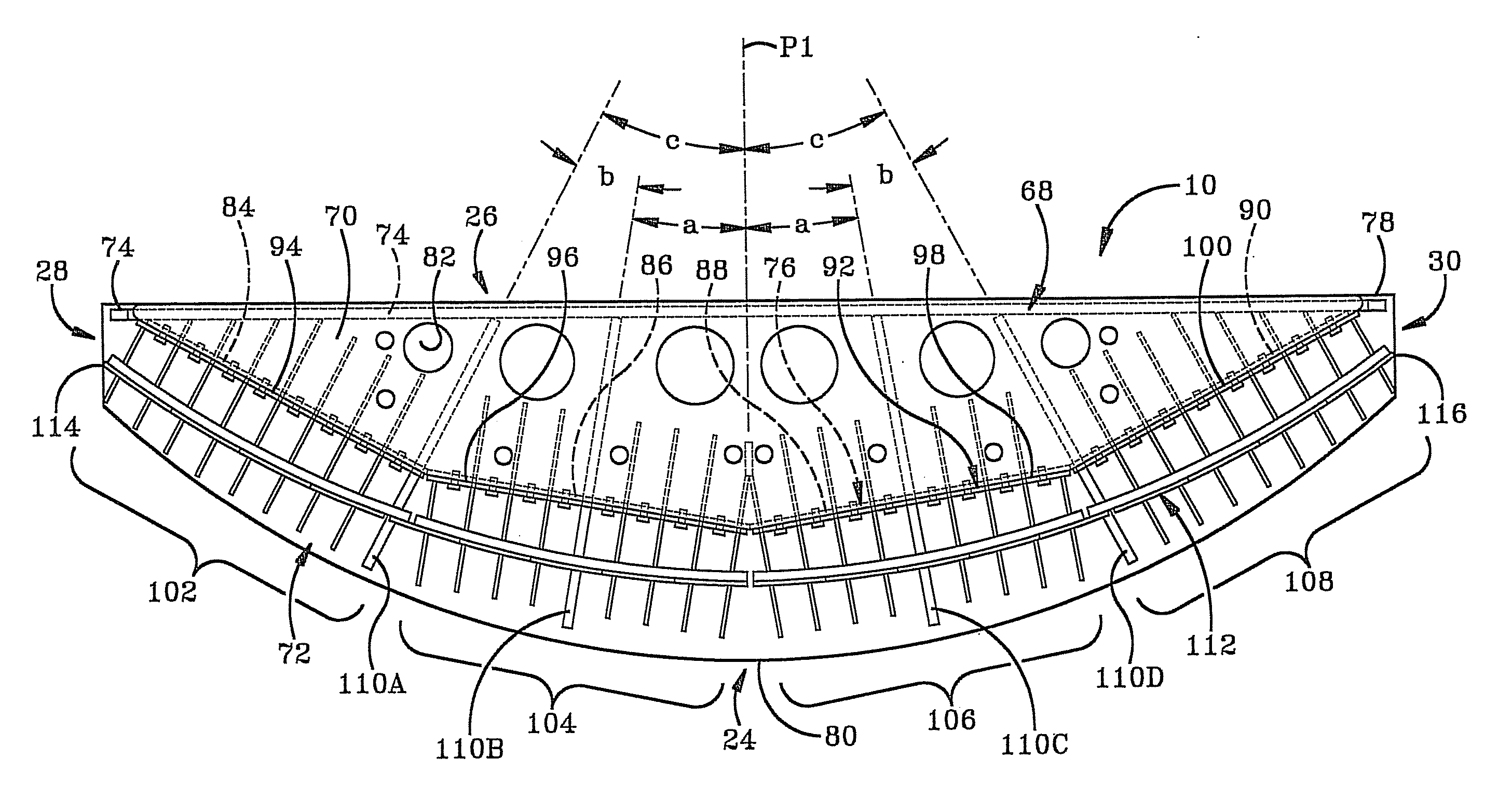
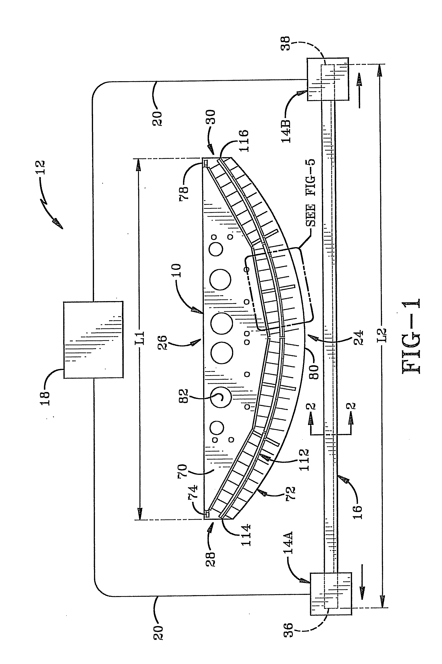
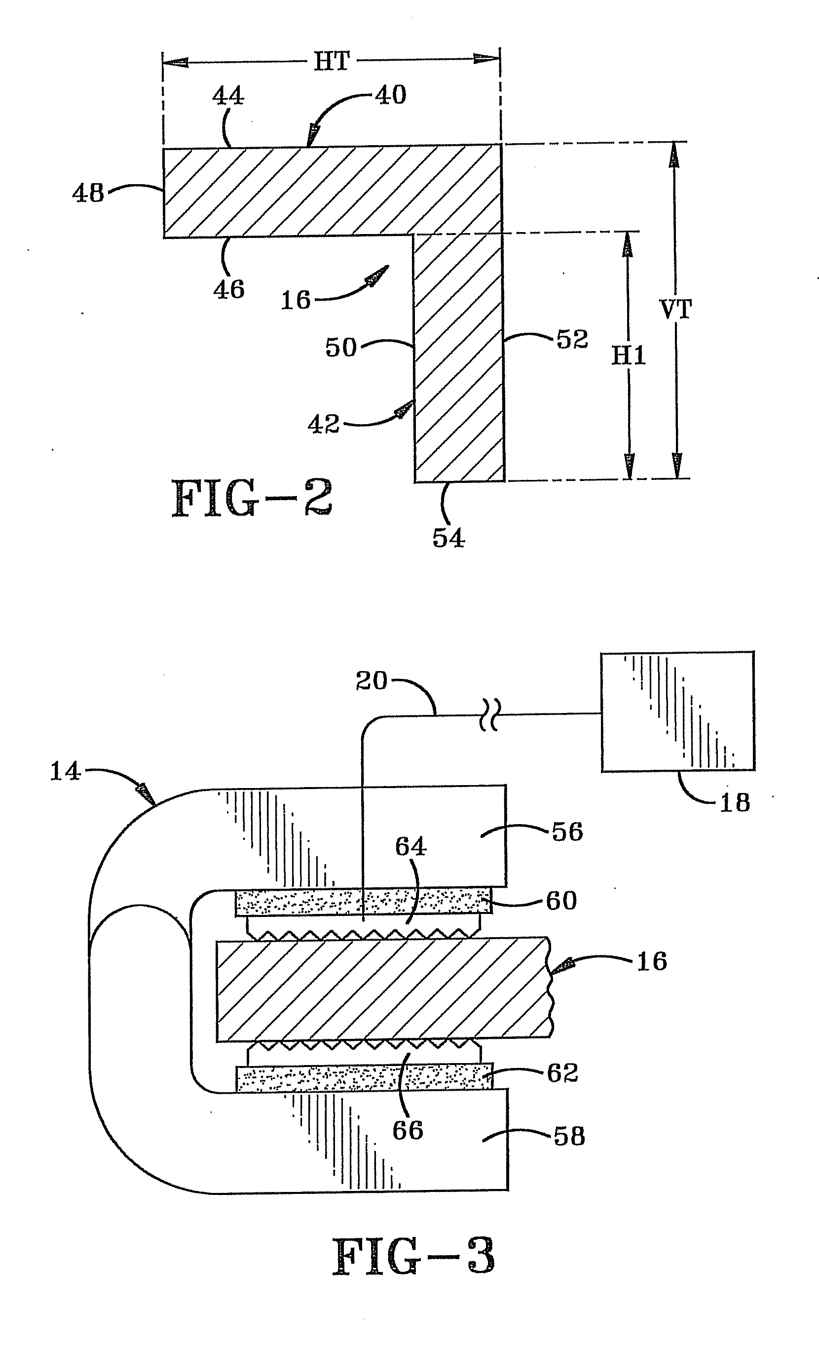
[0029]The die of the present invention is shown generally at 10 in FIG. 1 and is part of a hot stretch forming apparatus 12 which includes left and right jaws 14A and 14B which are configured to clamp the ends of a metal bar 16 to be shaped on die 10, an electric power source 18 and electrically conductive wires 20 in electrical communication with power source 18 and portions of the respective jaws 14A and 14B. More particularly, power source 18, wires 20, and portions of jaws 14A and B and metal bar 16 form an electrical circuit which may be selectively opened and closed in order to pass electrical current through metal bar 16 to heat metal bar 16 resistively due to its own electrical resistance. To prevent electrical shorting between metal bar 16 and die 10, a layer of electrical insulation such as layer 22 is positioned between the die face and metal bar to prevent contact between metal bar 16 and any metal portion of die 10 during the forming process. In the exemplary embodiment...


PUM

PropertyMeasurementUnit
length L1aaaaaaaaaa
length L1aaaaaaaaaa
temperatureaaaaaaaaaa

Abstract

A hot stretch wrap forming die typically includes a rigid backing section, a series of spaced ribs extending forward from the backing section, and an elongated face sheet secured to the ribs forward of the backing section with a convex forward-facing die face. The ribs elastically deflect during thermal expansion of the face sheet when a heated metal bar is forced against the die face so that the metal bar transfers heat to the face sheet. The die typically includes stiff ribs secured to the backing section and the face sheet which provide substantially fixed points for the face sheet during its thermal expansion. The face sheet may include several face sheet segments which together form the die face. The face sheet may also include contour plates which form respective portions of the die face and which may be used to adjust the specific contour of the die face.

Description

CROSS REFERENCE TO RELATED APPLICATIONS[0001]This application claims priority from U.S. Provisional Application Ser. No. 61 / 155,352 filed Feb. 25, 2009; the disclosure of which is incorporated herein by reference.BACKGROUND OF THE INVENTION[0002]1. Technical Field[0003]The present invention is related generally to a hot stretch forming die and a method of using the same. More particularly, the invention relates to such a die which is configured to minimize the distortion of the die due to thermal expansion during the process of forcing a heated metal work piece against the die face. Specifically, the invention relates to such a die which also includes an adjustable die face to allow for the adjustment of the contour of the die.[0004]2. Background Information[0005]It is well known in the art of hot stretch forming to wrap a heated metal bar around the work surface or die face of a rigid die in order to bend the metal bar into a shape conforming to the contour of the die face. However...

Claims


Application Information

Patent Timeline
Patent Type & Authority Applications(United States)
IPC IPC(8): B21D37/02
CPCB21D5/02B21D37/00B21D37/16B21D37/02
Inventor SCHIER, JOSEPH ALANSAN MARTIN, CARLOSFILLMORE, TIMOTHY P.
Owner HOWMET AEROSPACE INC
Learn More