Internal combustion engine with variable valve gear

a technology of variable valve gear and combustion engine, which is applied in the direction of combustion engine, valve arrangement, machine/engine, etc., can solve the problems of reduced combustion efficiency and reduced exhaust performance, and achieve the effect of improving combustibility and exhaust performan

Active Publication Date: 2010-08-26
MITSUBISHI MOTORS CORP
View PDF1 Cites 12 Cited by
  • Summary
  • Abstract
  • Description
  • Claims
  • Application Information

AI Technical Summary

Benefits of technology

[0009]Thus, the opening timing of the second intake valve is advanced ahead of that of the first intake valve in the start mode, so that swirls are generated as only the second intake valve opens

Problems solved by technology

Since the delay angle of the intake valves are limited in the start mode, according to the technique described in the above patent document, however, the intake valves share the same open period, so that fl

Method used


Image

  • Internal combustion engine with variable valve gear
  • Internal combustion engine with variable valve gear
  • Internal combustion engine with variable valve gear

Examples


Embodiment Construction

[0018]One embodiment of the present invention will now be described with reference to the accompanying drawings.

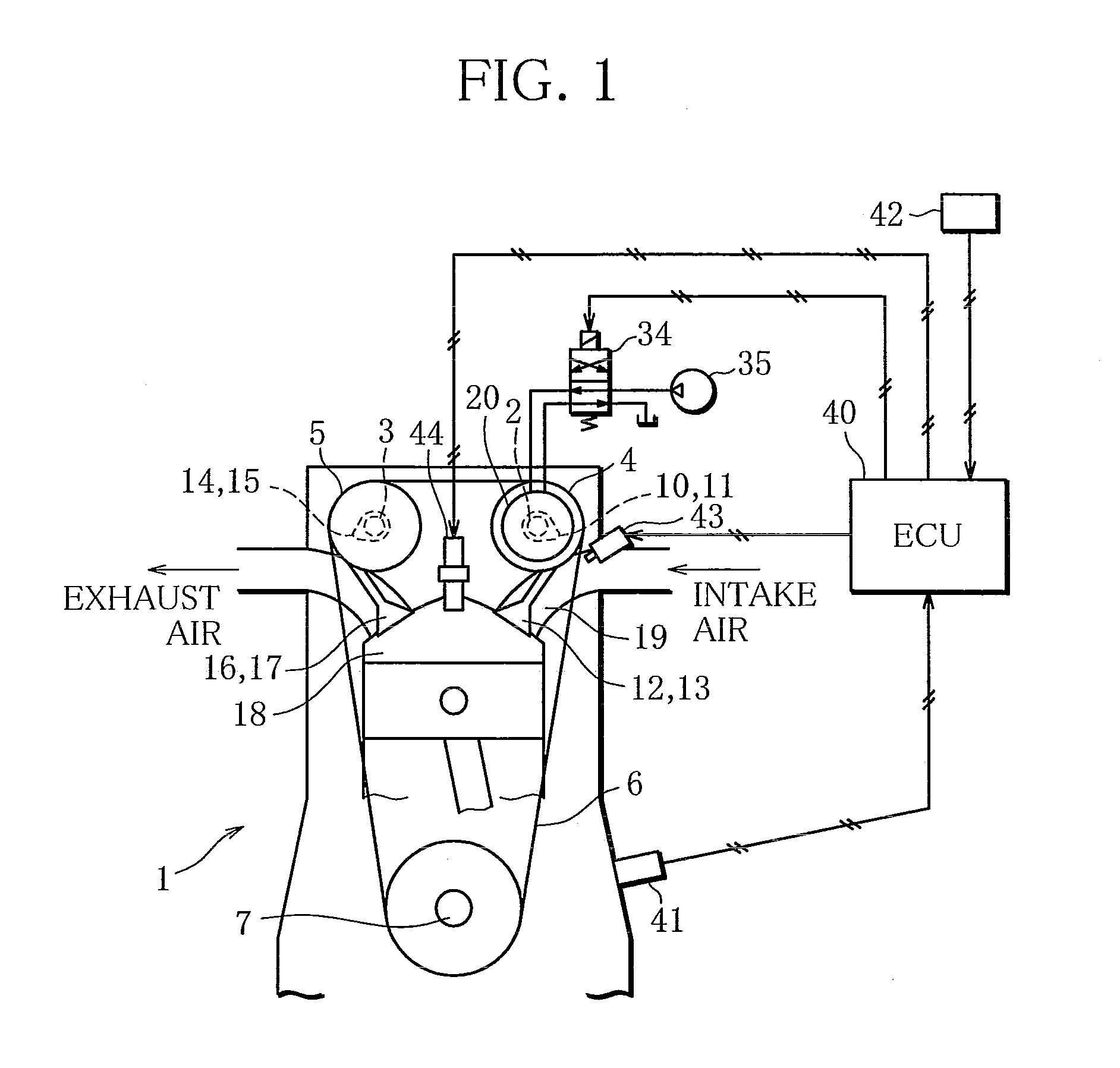
[0019]FIG. 1 is a schematic structure diagram of an internal combustion engine (engine 1) with a variable valve gear according to the present embodiment.

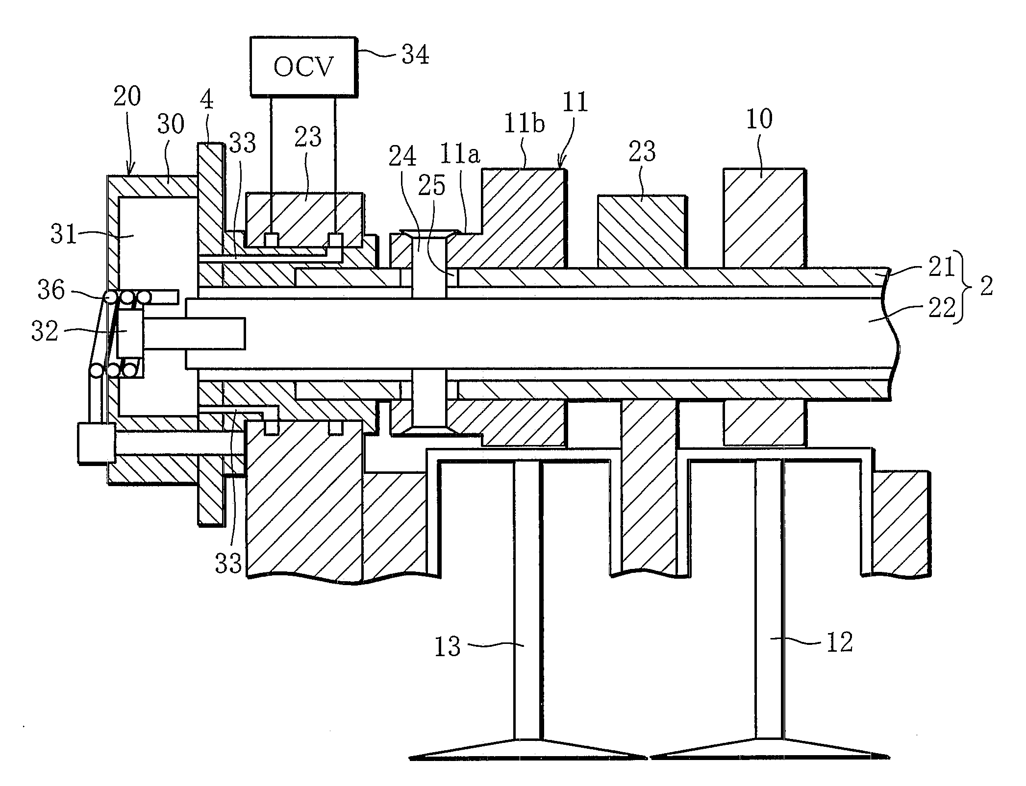
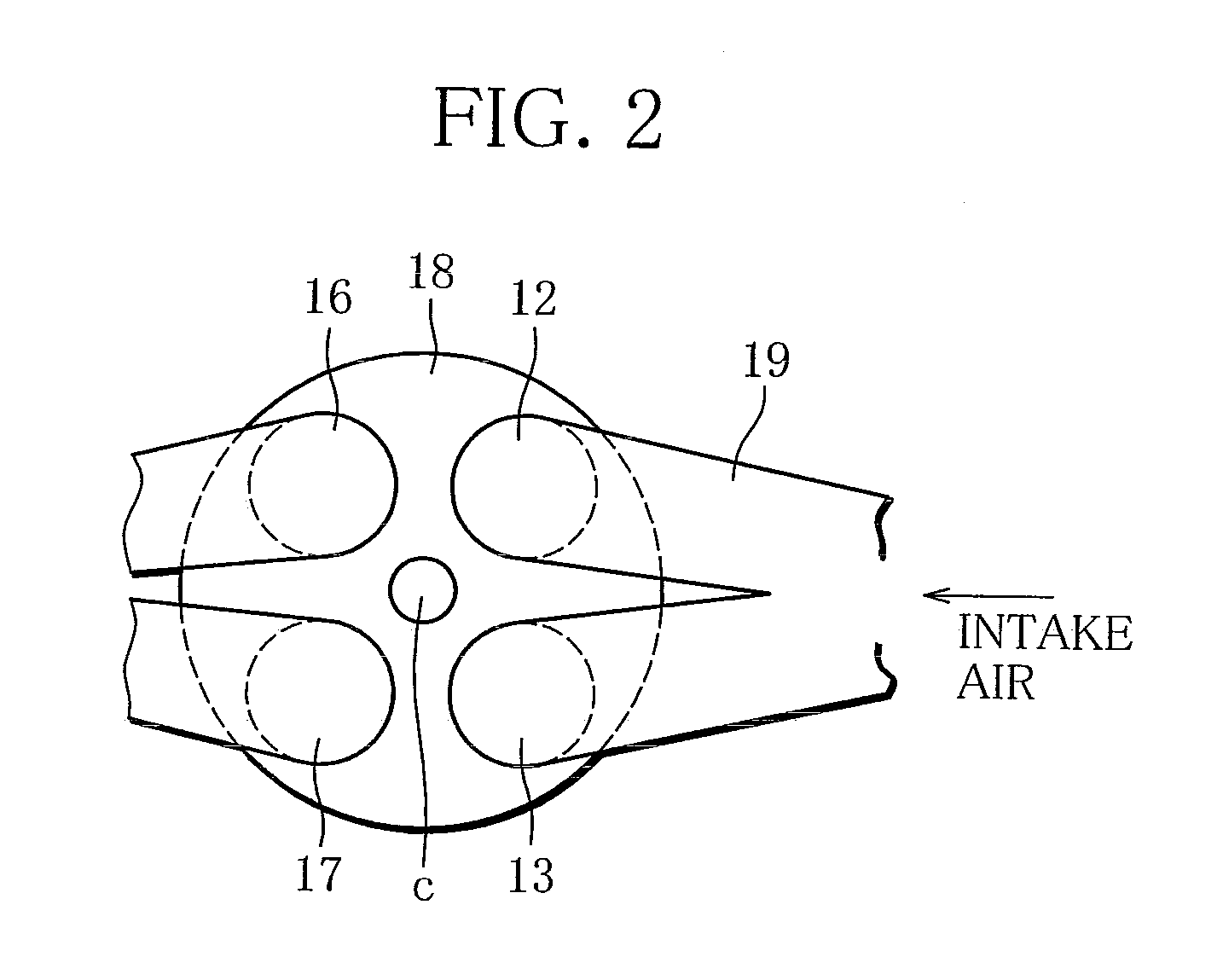
[0020]As shown in FIG. 1, the engine 1 of the present embodiment comprises a DOHC valve train. Cam sprockets 4 and 5 are connected, respectively, to the respective front ends of an intake camshaft 2 and an exhaust camshaft 3 of the engine 1. The cam sprockets 4 and 5 are coupled to a crankshaft 7 by a chain 6. As the crankshaft 7 rotates, the intake and exhaust camshafts 2 and 3 are rotated together with the cam sprockets 4 and 5. Intake valves 12 and 13 are opened and closed by intake cams 10 and 11 on the intake camshaft 2, and exhaust valves 16 and 17 by exhaust cams 14 and 15 on the exhaust camshaft 3. A combustion chamber 18 of the engine 1 is pent-roof-shaped.

[0021]FIG. 2 is a reference diagram showing a layout of th...


PUM


Abstract

In an engine which comprises a first intake valve and a second intake valve for each cylinder, configured to be driven by a first intake cam and a second intake cam, respectively, and a cam phase change mechanism configured to vary the phase of the second intake cam, the cam phase change mechanism is controlled so that the opening timing of the second intake valve is advanced ahead of that of the first intake valve in a start mode.

Description

BACKGROUND OF THE INVENTION[0001]1. Field of the Invention[0002]The present invention relates to an internal combustion engine with a cam phase change mechanism capable of changing the phase of an intake cam.[0003]2. Description of the Related Art[0004]Conventionally, there are internal combustion engines that comprise a cam phase change mechanism as a variable valve gear, which changes the phase of an intake cam to vary the opening and closing timings of an intake valve. Further, a technique has been developed in which the cam phase change mechanism is applied to internal combustion engines that are provided with a plurality of intake valves for each cylinder. According to this technique, the opening and closing timings of only some of the intake valves are varied in accordance with the load and engine speed.[0005]In one such internal combustion engine, the opening and closing timings of some of the intake valves are delayed in, for example, a high-speed, high-load mode, whereby th...

Claims


Application Information

Patent Timeline
IPC IPC(8): F01L1/34
CPCF01L1/053F01L1/34F01L1/3442F01L2001/0473Y02T10/18F01L2800/06F02D13/0238F02D13/0257F01L2001/34493Y02T10/12
Inventor MURATA, SHINICHI
Owner MITSUBISHI MOTORS CORP
Why Eureka
Try Eureka